Toyota Sienna Service Manual: Reassembly
1. INSTALL FRONT DOOR WIRE LH
- Install the wire with the 2 bolts.
Torque: Reference 8.0 N*m (82 kgf*cm, 71 in.*lbf)
NOTICE: In order to prevent water leakage, be sure that the lip of the rubber grommet does not turn up or is not deformed when installing the wire.
- Connect the wire clips.
2. INSTALL FRONT DOOR CHECK ASSEMBLY LH
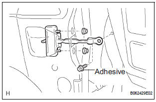
- Apply MP grease to the sliding area of the door check.
- Install the door check to the door panel with the 2
nuts.
Torque: 5.5 N*m (56 kgf*cm, 49 in.*lbf) HINT: Install the door check so that the rivet head is up.
- Apply adhesive to the threads of the bolt.
Adhesive: Part No. 08833-00070, THREE BOND 1324 or equivalent
- Install the door check to the body with the bolt.
Torque: 26 N*m (265 kgf*cm, 19 ft.*lbf)
3. INSTALL FRONT DOOR OUTSIDE HANDLE FRAME SUB-ASSEMBLY LH
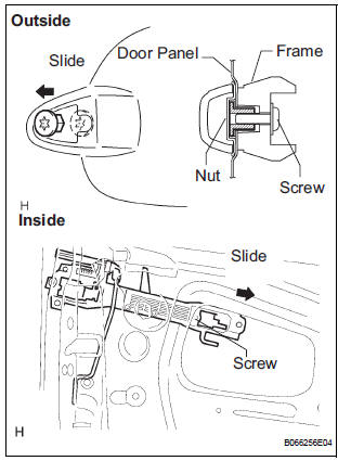
- Install the open rod to the outside handle frame.
- Slide the outside handle frame in the indicated by the arrow mark in the illustration.
- Using a torx socket wrench (T30), install the outside
handle frame with the screw.
Torque: 4.0 N*m (41 kgf*cm, 35 in.*lbf) NOTICE: Insert a cover between the nut and the door panel.
- Install the outside handle pads front and rear.
4. INSTALL FRONT DOOR HANDLE ASSEMBLY OUTSIDE LH
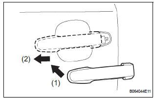
- Install the outside handle by pushing in the direction indicated by the arrow mark in the illustration.
NOTICE: If the release plate is not pulled and held when installing the outside handle, it will strike against with the outside handle and become damaged.
5. INSTALL FRONT DOOR WITH MOTOR LOCK ASSEMBLY LH
- Apply MP grease to the sliding and area of the door lock.
- Install a new door lock wire harness packing to the door lock.
NOTICE:
- When reusing a door lock that has been removed, replace the packing in the connecting part with new packing.
- Be careful that no grease or dirt sticks to the packing surface in the connecting part.
- Reusing removed packing or using damaged packing will allow water to penetrate through to the connecting part, resulting in a malfunction of the door lock.
- Insert the open rod into the lock and then set it to the door panel.
NOTICE: Make sure that the outside handle link is securely engaged with the door lock.
- Apply adhesive to the threads of the screws.
Adhesive: Part No. 08833-00070, THREE BOND 1324 or equivalent
- Using a torx socket wrench (T30), install the lock
with the 3 screws.
Torque: 5.0 N*m (51 kgf*cm, 42 in.*lbf)
- Connect the lock connector.
6. INSTALL FRONT DOOR OUTSIDE HANDLE COVER
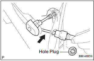
- Using a torx socket wrench (T30), install the outside
handle cover with the screw.
Torque: 4.0 N*m (41 kgf*cm, 35 in.*lbf)
- Install the hole plug.
7. INSTALL FRONT DOOR FRAME SUB-ASSEMBLY REAR LOWER LH
- Install the frame with the bolt.
Torque: 8.0 N*m (82 kgf*cm, 71 in.*lbf)
8. INSTALL POWER WINDOW REGULATOR MOTOR ASSEMBLY LH
- Using a torx driver (T25), install the regulator motor
with the 3 screws.
Torque: 5.4 N*m (55 kgf*cm, 48 in.*lbf)
HINT: Never rotate the motor assembly counterclockwise until the window glass installation is done.
9. INSTALL FRONT DOOR WINDOW REGULATOR SUBASSEMBLY LH
- Apply MP grease to the sliding and rotating parts of the window regulator.
NOTICE: Do not apply grease to the spring of the window regulator.
- Install the window regulator with 6 bolts.
Torque: 8.0 N*m (82 kgf*cm, 71 in.*lbf)
- Connect the window regulator connector.
NOTICE: Be careful not to drop the door window regulator as this may cause deformation.
10. INSTALL FRONT DOOR GLASS SUB-ASSEMBLY LH
NOTICE: Do not damage the door glass.
- Install the glass run.
- Insert the door glass into the door panel along the glass run in the direction indicated by the arrow mark in the illustration.
- Install the door glass to the window regulator with
the 2 bolts.
Torque: 5.5 N*m (56 kgf*cm, 49 in.*lbf)
- Reset the power window motor (See page WS-5).
- Inspect operation of the power window.
HINT: When the installation point of the door glass does not match, adjust the regulator position in manual operation.
- Connect the power window switch to the wire harness and turn the ignition switch ON.
- Repeat UP and DOWN operation several times in manual operation.
11. INSTALL OUTER REAR VIEW MIRROR ASSEMBLY LH
- Install the mirror with the 3 nuts.
Torque: 8.0 N*m (82 kgf*cm, 71 in.*lbf)
- Connect the mirror connector.
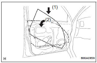
12. INSTALL FRONT DOOR SERVICE HOLE COVER LH
- Apply butyl tape to the door panel, as shown in the illustration.
- Install the service hole cover.
HINT:
- When installing the service hole cover, pull out the links and connectors through the service hole cover.
- There should be no wrinkles or folds after attaching the service hole cover.
- After attaching the service hole cover, confirm the sealing condition.
 Adjustment
HINT:
On the RH side, use the same procedures as on the LH
side.
Since a centering bolt is used as a door hinge mounting
bolt on the body side and the door side, the door can not
be adjust ...
 Slide door
COMPONENTS
...
Other materials:
Disassembly
1. REMOVE NO. 2 FRONT AXLE INBOARD JOINT BOOT LH CLAMP
(a) Using pliers, remove the No. 2 front axle inboard
joint boot LH clamp, as shown in the illustration.
2. REMOVE FRONT AXLE INBOARD JOINT BOOT LH
CLAMP
(a) Remove the front axle inboard joint boot LH clamp
using the same procedures a ...
Idle Control System Malfunction
DTC P0505 Idle Control System Malfunction
DESCRIPTION
The idling speed is controlled by the ETCS (Electronic Throttle Control
System). The ETCS is comprised
of: 1) the one valve type throttle body; 2) the throttle actuator, which
operates the throttle valve; 3) the
Throttle Position (TP) sen ...
Trouble in Passenger Airbag ON / OFF Indicator
DESCRIPTION
The occupant classification system detects the front passenger seat
condition. It then informs a
passenger of the front passenger airbag, the front seat side airbag RH and front
seat belt pretensioner
RH condition (activated/not activated) by the passenger airbag ON/OFF indicator. ...
