Toyota Sienna Service Manual: Reassembly
1. INSTALL REAR DOOR WIRE SUB-ASSEMBLY LH
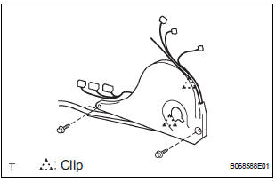
- Install the wire.
NOTICE: When installing the wire, push the areas where the clips are installed in order to prevent damage and deformation.
- Install the 2 screws
2. INSTALL REAR DOOR LOCK ASSEMBLY LH
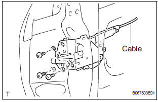
- Apply MP grease to the sliding and rotating areas of the lock.
- Apply adhesive to the threads of the screws.
Adhesive: Part No. 08833-00070, THREE BOND 1324 or equivalent
- Install the lock to the door panel with the 3 screws.
Torque: 5.0 N*m (51 kgf*cm, 44 in.*lbf)
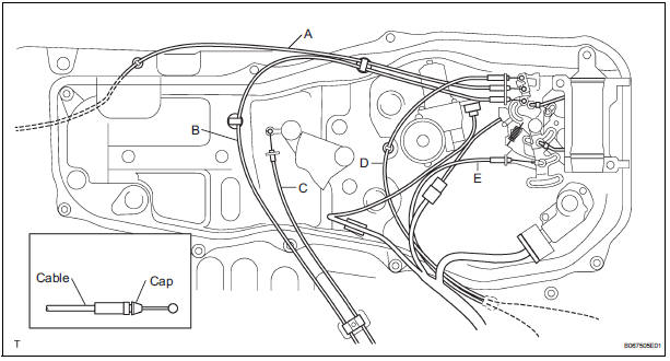
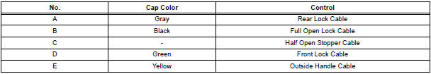
- Connect the cable.
3. INSTALL SLIDE DOOR LOCK ASSEMBLY FRONT LH
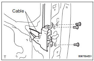
- Apply MP grease to the sliding and rotating areas of the lock.
- Apply adhesive to the threads of the screws.
Adhesive: Part No. 08833-00070, THREE BOND 1324 or equivalent
- Install the lock front to the door panel with the 3
screws.
Torque: 5.0 N*m (51 kgf*cm, 44 in.*lbf)
- Connect the 2 cables.
4. INSTALL REAR DOOR OUTSIDE HANDLE FRAME SUB-ASSEMBLY LH
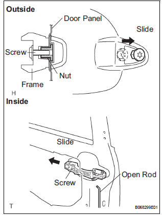
- Apply MP grease to the sliding and rotating parts of the outside handle frame.
- Slide the outside handle frame in the direction indicated by the arrow mark in the illustration.
- Using a torx socket wrench (T30), install the outside
handle frame with the screw.
Torque: 7.0 N*m (71 kgf*cm, 62 in.*lbf) NOTICE: Insert a cover between the nut and the door panel.
- Install the open rod.
5. INSTALL REAR DOOR OUTSIDE HANDLE ASSEMBLY LH
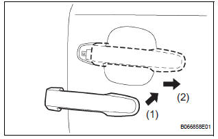
- Install the outside handle pads front and rear.
- Pushing the outside handle in the direction indicated by the arrow mark in the illustration, install the outside handle.
NOTICE: If the release plate is not pulled and held when installing the outside handle, it will strike against with the outside handle and become damaged.
6. INSTALL REAR DOOR OUTSIDE HANDLE COVER LH
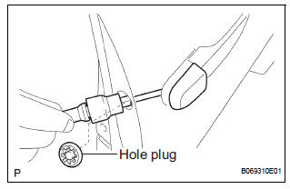
- Using a torx socket wrench (T30), install the outside
handle cover with the screw.
Torque: 7.0 N*m (71 kgf*cm, 62 in.*lbf)
- Install the hole plug.
7. INSTALL REAR DOOR STIFFENER CUSHION LH
- Install the 2 grommets and 2 clips.
- Install the stiffener cushion with the clip and 2 screws.
8. INSTALL SLIDE DOOR ATTACHMENT CONTROL LH
- Temporarily install the window frame rear lower with the nut.
- Move the window frame rear lower in the direction indicated by the arrow mark in the illustration.
- Apply MP grease to the sliding and rotating areas of the window regulator.
- Install the window regulator with the 4 bolts.
Torque: 7.0 N*m (71 kgf*cm, 62 in.*lbf)
- Install the half stop control lever and door lock control bellcrank.
- Install the power window regulator motor with the 3
screws.
Torque: 5.5 N*m (58 kgf*cm, 49 in.*lbf)
- Apply MP grease to the sliding and rotating areas of the lock remote control.
- Install the lock remote control with the 3 bolts.
Torque: 5.5 N*m (58 kgf*cm, 49 in.*lbf)
- Apply MP grease to the sliding and rotating areas of the lock actuator.
- Install the lock actuator with 2 screws.
Torque: 5.5 N*m (58 kgf*cm, 49 in.*lbf)
- Install the attachment control with the 8 bolts.
Torque: 8.0 N*m (82 kgf*cm, 71 in.*lbf)
- Install the inside handle with the 2 screws and bolt.
Torque: 7.0 N*m (71 kgf*cm, 62 in.*lbf)
- Install the control cables and the wires.
9. INSTALL SLIDE DOOR WINDOW ASSEMBLY LH
- Open the door glass until the bolts appear in the service holes.
- Install the window with the 2 bolts.
Torque: 8.0 N*m (82 kgf*cm, 71 in.*lbf)
- Install the hole plug.
- Put the window frame rear lower in the original
position and tighten the nut.
Torque: 8.0 N*m (82 kgf*cm, 71 in.*lbf)
- Install the bolt.
Torque: 8.0 N*m (82 kgf*cm, 71 in.*lbf)
- Install the window frame with the bolt.
Torque: 8.0 N*m (82 kgf*cm, 71 in.*lbf)
- Install the glass run.
 Reassembly
1. INSTALL REAR DOOR WIRE SUB-ASSEMBLY LH
Install the wire.
NOTICE:
When installing the wire, push the areas where
the clips are installed in order to prevent
damage and deformation.
...
 Installation
1. INSTALL SLIDE DOOR ROLLER ASSEMBLY UPPER
Apply MP grease to the rotating areas of the roller.
Install the roller with the 2 bolts.
Torque: 13 N*m (130 kgf*cm, 10 ft.*lbf)
2. INSTALL ...
Other materials:
Headlight dimmer switch
COMPONENTS
REMOVAL
1. REMOVE STEERING COLUMN LOWER COVER
2. REMOVE STEERING COLUMN UPPER COVER
3. REMOVE HEADLIGHT DIMMER SWITCH ASSEMBLY
Disconnect the connector.
Release the claw fitting and remove the headlight
dimmer switch assembly.
INSPECTION
1. HEADLIGHT DI ...
Inspection
1. INSPECT THERMOSTAT
(a) Inspect the thermostat.
HINT:
The valve opening temperature is inscribed on the
thermostat.
(b) Immerse the thermostat in water and gradually heat
the water.
(c) Check the valve opening temperature.
Valve opening temperature:
80 to 84°C (176 to 183°F) ...
Evaporative Emission System Switching Valve
Control Circuit High
DTC P2420 Evaporative Emission System Switching Valve
Control Circuit High
DTC SUMMARY
DESCRIPTION
The circuit description can be found in the EVAP (Evaporative Emission)
System.
INSPECTION PROCEDURE
Refer to the EVAP System.
MONITOR DESCRIPTION
5 hours*1 after the ignition switch is t ...
