Toyota Sienna Service Manual: Reassembly
1. INSTALL POWER SLIDE DOOR TOUCH SENSOR LH
- Install the touch sensor with the 4 screws.
- Connect the connector.
- Fix the wire harness inside the door panel with the clip.
2. INSTALL REAR DOOR WIRE SUB-ASSEMBLY LH
- Install the wire.
NOTICE: When installing the wire, push the areas where the clips are installed in order to prevent damage and deformation. (b) Install the 2 screws.
- Install the 2 screws.
3. REMOVE POWER SLIDE DOOR LOCK ASSEMBLY LH
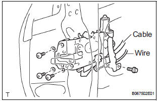
- Apply MP grease to the sliding and rotating areas of the lock.
- Apply adhesive to the threads of the 3 screws.
Adhesive: Part No. 08833-00070, THREE BOND 1324 or equivalent
- Using a torx socket wrench (T30), install the lock to
the door panel with the 3 screws.
Torque: 5.0 N*m (51 kgf*cm, 44 in.*lbf)
- Install the bolt.
Torque: 5.0 N*m (51 kgf*cm, 44 in.*lbf)
- Connect the connector and cable.
4. INSTALL SLIDE DOOR LOCK ASSEMBLY FRONT LH
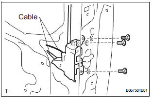
- Apply MP grease to the sliding and rotating areas of the lock.
- Apply adhesive to the threads of the 3 screws.
Adhesive: Part No. 08833-00070, THREE BOND 1324 or equivalent
- Using a torx socket wrench (T30), install the lock to
the door panel with the 3 screws.
Torque: 5.0 N*m (51 kgf*cm, 44 in.*lbf)
- Connect the 2 cables.
5. INSTALL REAR DOOR STIFFENER CUSHION LH
- Install the 2 grommets and 2 clips.
- Install the stiffener cushion with the clip and 2 screws
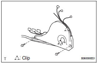
6. INSTALL POWER SLIDE DOOR CONTROL MOTOR AND CLUTCH
- Tighten the 4 bolts on the lower part of the control
motor and clutch.
Torque: 8.0 N*m (82 kgf*cm, 71 in.*lbf)
- Fix the wires with the 2 clips respectively.
- RH side: Tighten the bolt indicated by the arrow in the illustration together with the earth wire.
- Tighten the 3 bolts on the upper part of the control
motor and clutch.
Torque: 8.0 N*m (82 kgf*cm, 71 in.*lbf)
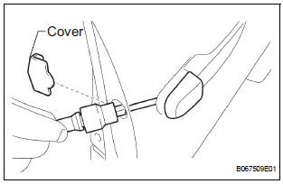
7. INSTALL REAR DOOR OUTSIDE HANDLE FRAME SUB-ASSEMBLY LH
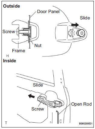
- Apply MP grease to the sliding and rotating areas of the frame.
- Slide the outside handle frame in the indicated by the arrow mark in the illustration.
- Using a torx socket wrench (T30), install the frame
with the screw as shown in the illustration.
Torque: 7.0 N*m (71 kgf*cm, 62 in.*lbf) NOTICE: Insert a cover between the nut and door panel.
- Install the open rod.
8. INSTALL REAR DOOR OUTSIDE HANDLE ASSEMBLY LH
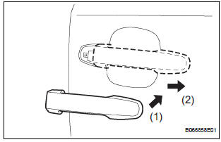
- Install the outside handle pads front and rear.
- Pushing the handle in the direction indicated by the arrow mark in the illustration, install the handle.
NOTICE: If the release plate is not pulled and held when installing the outside handle, it will strike against with the outside handle and become damaged.
9. INSTALL REAR DOOR OUTSIDE HANDLE COVER LH
- Using a torx socket wrench (T30), install the outside
handle cover with the screw.
Torque: 7.0 N*m (71 kgf*cm, 62 in.*lbf)
- Install the outside handle hole cover.
10. INSTALL SLIDE DOOR ATTACHMENT CONTROL LH
- Temporarily install the window frame rear lower with the nut.
- Move the window frame rear lower in the direction indicated by the arrow mark in the illustration.
- Apply MP grease to the sliding and rotating areas of the window regulator.
- Install the window regulator with the 4 bolts.
Torque: 7.0 N*m (71 kgf*cm, 62 in.*lbf)
- Install the half stop control lever and door lock control bellcrank.
- Install the power window regulator motor with the 3
screws.
Torque: 5.5 N*m (58 kgf*cm, 49 in.*lbf)
- Apply MP grease to the sliding and rotating areas of the door lock remote control.
- Install the lock remote control with the 3 bolts.
Torque: 5.5 N*m (58 kgf*cm, 49 in.*lbf)
- Install the lock release motor with the 2 screws.
Torque: 5.5 N*m (58 kgf*cm, 49 in.*lbf)
- Install the control rod.
- Install the lock actuator with the 2 screws.
Torque: 5.5 N*m (58 kgf*cm, 49 in.*lbf)
- Install the control rod.
- LH side:
Install the attachment control with the 8 bolts.
Torque: 8.0 N*m (82 kgf*cm, 71 in.*lbf)
- RH side:
Install the attachment control with the 6 bolts.
Torque: 8.0 N*m (82 kgf*cm, 71 in.*lbf)
- RH side:
Tighten the 2 bolts indicated by the arrow together
with the earth wire.
Torque: 8.0 N*m (82 kgf*cm, 71 in.*lbf)
- Install the inside handle with the 2 screws and bolt.
Torque: 7.0 N*m (71 kgf*cm, 62 in.*lbf)
- Install the control rod.
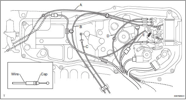
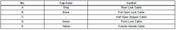
- Install the control cables and the wires.
11. INSTALL SLIDE DOOR WINDOW ASSEMBLY LH
- Open the door glass until the bolts appear in the service holes.
- Install the window with the 2 bolts.
- Install the hole plug.
- Put the window frame rear lower in the original
position and tighten the nut.
Torque: 8.0 N*m (82 kgf*cm, 71 in.*lbf)
- Install the bolt.
Torque: 8.0 N*m (82 kgf*cm, 71 in.*lbf)
- Install the window frame with the bolt.
Torque: 8.0 N*m (82 kgf*cm, 71 in.*lbf)
- Install the glass run.
 Adjustment
HINT:
On the RH side, use the same procedures as on the LH side.
1. INSPECT SLIDE DOOR PANEL SUB-ASSEMBLY LH
Check that the clearance is within the standard
range.
Standard
2. ADJUST ...
 Installation
1. INSTALL SLIDE DOOR ROLLER ASSEMBLY UPPER
Apply MP grease to the rotating area of the roller.
Install the roller with the 2 bolts.
Torque: 13 N*m (130 kgf*cm, 10 ft.*lbf)
2. INSTALL S ...
Other materials:
Data list / active test
1. USING INTELLIGENT TESTER
Connect the intelligent tester to the DLC3.
Monitor the ECU data by following the prompts on
the tester screen.
HINT:
The intelligent tester has a "Snapshot" function
which records the monitored data.
Refer to the intelligent tester o ...
CAN Bus Line
DESCRIPTION
When any DTC for the CAN communication system is output, first measure the
resistance between the
terminals of the DLC3 to specify the trouble area, and check that there is no
short in the CAN main wire,
between the main wire, and +B or GND.
WIRING DIAGRAM
INSPECTION PRO ...
Correct use of the seat belts
Extend the shoulder belt so that
it comes fully over the shoulder,
but does not come into contact
with the neck or slide off the
shoulder.
Position the lap belt as low as
possible over the hips.
Adjust the position of the seatback.
Sit up straight and well
back in the seat.
...
