Toyota Sienna Service Manual: Reassembly
1. INSTALL CENTER SUPPORT BEARING ASSEMBLY NO.1
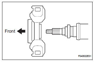
(a) Set the center support bearing assembly No. 1 (front) to the intermediate shaft, as shown in the illustration.
(b) Install a new washer to the intermediate shaft.
NOTICE: Be sure to install the bearing in the correct direction.
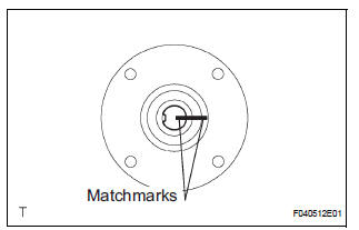
(c) Align the matchmarks on the front flange and shaft, and place the flange on the shaft.
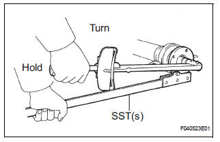
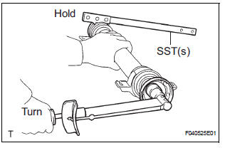
(d) Using SST(s) to hold the front flange, press the center support bearing assembly No. 1 (front) into the position by tightening down with a new nut and plate washer.
SST 09330-00021 Torque: 181 N*m (1,850 kgf*cm, 134 ft.*lbf)
(e) Loosen the nut.
(f) Torque the nut again.
Torque: 69 N*m (700 kgf*cm, 51 ft.*lbf)
(g) Using a chisel and a hammer, stake the nut.
2. INSTALL CENTER SUPPORT BEARING ASSEMBLY NO.1
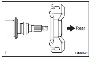
(a) Set the center support bearing assembly No. 1 (rear) on the shaft, as shown in the illustration.
(b) Install a new washer to the shaft.
NOTICE: Be sure to install the bearing in the correct direction.
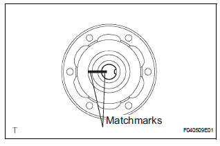
(c) Align the matchmarks on the rear flange and shaft, and place the flange on the shaft.
(d) Using SST(s) to hold the front flange, press the center support bearing assembly No. 1 (rear) into the position by tightening down with a new nut and plate washer.
SST 09330-00021 Torque: 181 N*m (1,850 kgf*cm, 134 ft.*lbf)
(e) Loosen the nut.
(f) Torque the nut again.
Torque: 69 N*m (700 kgf*cm, 51 ft.*lbf)
(g) Using a chisel and a hammer, stake the nut.
3. INSTALL INTERMEDIATE SHAFT
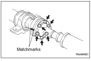
(a) Align the matchmarks on the intermediate shaft and rear propeller shaft assembly rear, then install the 2 washers and 6 bolts.
(b) Using a hexagon wrench (6 mm), loosely tighten the 6 bolts.
4. INSTALL PROPELLER SHAFT ASSEMBLY
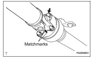
(a) Align the matchmarks on the propeller shaft assembly flange and front flange, and connect the shaft with the 4 bolts, washers and nuts.
Torque: 74 N*m (750 kgf*cm, 54 ft.*lbf)
(b) Check that each joint of the propeller shaft is facing in the correct direction, as shown in the illustration below.
 Inspection
1. INSPECT SPIDER BEARING
(a) Check that the spider bearing moves smoothly by
turning the flange.
(b) Check for the looseness around the joint by strongly
moving the flange in the axial and ...
 Installation
1. INSTALL PROPELLER W/CENTER BEARING SHAFT ASSEMBLY
(a) Align the matchmarks on the propeller shaft
assembly rear flange and differential companion
flange, and connect the shaft with the 4 bol ...
Other materials:
Using the mechanical key (vehicles with a smart key system)
To take out the mechanical key,
push the release button and take
the key out.
The mechanical key can only be
inserted in one direction, as the
key only has grooves on one side.
If the key cannot be inserted in a
lock cylinder, turn it over and reattempt
to insert it.
After using t ...
Adjustment
HINT:
On the RH side, use the same procedures as on the LH
side.
Since a centering bolt is used as a door hinge mounting
bolt on the body side and the door side, the door can not
be adjusted with it on. Substitute a bolt with a washer for
the centering bolt.
1. INSPECT FRONT DOOR PA ...
Installation with LATCH system (third seat)
Manual seat
Fold the seatback while pulling
the strap. Return the seatback
and secure it at the 1st lock
position (most upright position).
Adjust the seatback to the
11th lock position.
1st lock position
11th lock position
Power seat
Fold down the seatb ...
