Toyota Sienna Service Manual: Removal
1. REMOVE FRONT WHEEL
2. REMOVE FRONT AXLE HUB LH NUT
HINT: (See page AH-4) SST 09930-00010
3. SEPARATE SPEED SENSOR FRONT LH
HINT: (See page AH-4)
4. SEPARATE FRONT DISC BRAKE CALIPER ASSEMBLY LH
HINT: (See page AH-4)
5. REMOVE FRONT DISC
6. SEPARATE TIE ROD ASSEMBLY LH
HINT: (See page AH-4) SST 09628-62011
7. SEPARATE FRONT SUSPENSION ARM SUBASSEMBLY LOWER NO.1 LH
HINT: (See page AH-4)
8. REMOVE FRONT AXLE ASSEMBLY LH
HINT: (See page AH-4)
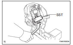
9. REMOVE LOWER BALL JOINT ASSEMBLY FRONT LH
a) Remove the cotter pin and nut.
(b) Using SST, remove the lower ball joint assembly front LH.
SST 09628-62011
 Front lower ball joint
COMPONENTS
...
 Inspection
1. INSPECT LOWER BALL JOINT ASSEMBLY FRONT LH
(a) As shown in the illustration, flip the ball joint stud
back and forth 5 times, before installing the nut.
(b) Using a torque wrench, turn the ...
Other materials:
Camshaft Position "A" Actuator Circuit
DTC P0010 Camshaft Position "A" Actuator Circuit (Bank
1)
DTC P0020 Camshaft Position "A" Actuator Circuit (Bank
2)
DESCRIPTION
The Variable Valve Timing (VVT) system includes the ECM, Oil Control Valve (OCV)
and VVT controller.
The ECM sends a target duty-cycle control ...
Adjustment
1. INSPECT SHIFT LEVER POSITION
(a) When shifting from P to R position only with ignition
switch ON and brake pedal, make sure that the
shifting lever moves smoothly and can be
moderately operated.
(b) When starting engine, make sure that the vehicle
moves forward when shifting from N to D p ...
EVAP System
RELATED DTCS
If any EVAP system DTCs are set, the malfunctioning area can be determined
using the table below.
NOTICE:
If the 0.02 inch reference pressure difference between the first and
second checks is greater than
the specification, the DTCs corresponding to the refe ...
