Toyota Sienna Service Manual: Removal
1. SEPARATE BATTERY NEGATIVE TERMINAL
2. REMOVE FRONT DOOR SCUFF PLATE LH
3. REMOVE COWL SIDE TRIM BOARD LH
4. REMOVE INSTRUMENT PANEL FINISH PANEL SUBASSEMBLY LOWER LH
(a) Remove the 2 bolts and instrument panel finish panel sub-assembly lower LH.
5. REMOVE INSTRUMENT PANEL SAFETY PAD INSERT SUB-ASSEMBLY NO. 1
(a) Remove the 4 bolts and instrument panel safety pad insert sub-assembly No. 1.
6. LOOSEN BRAKE PEDAL SHAFT
(a) Loosen the 2 brake pedal shafts.
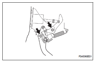
7. REMOVE BRAKE PEDAL SUPPORT ASSEMBLY
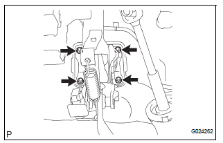
(a) Remove the 4 nuts and brake pedal support subassembly.
(b) Using needle-nose pliers, remove the tension spring.
(c) Remove the clip and clevis pin from the brake pedal lever.
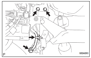
(d) Remove the 2 bolts from the brake pedal bracket No. 3.
(e) Remove the stop light switch harness clamp from the brake pedal support sub-assembly.
(f) Disconnect the stop light switch connector.
 On-vehicle inspection
1. INSPECT BRAKE PEDAL HEIGHT
(a) Check the brake pedal height.
Pedal height from dash panel:
150.3 to 160.3 mm (5.917 to 6.311 in.)
NOTICE:
Do not adjust the pedal height. Doing so by
chang ...
 Disassembly
1. REMOVE STOP LIGHT SWITCH ASSEMBLY
(a) Turn the stop light switch assembly
counterclockwise and remove the stop light switch
assembly.
(b) Remove the stop light switch mounting adjuster
from ...
Other materials:
Removal
1. DISCONNECT CABLE FROM NEGATIVE BATTERY
TERMINALV
Caution:
wait at least 90 seconds after disconnecting the
cable from the negative (-) battery terminal to
prevent airbag and seat belt pretensioner activation.
2. Remove air fuel ratio sensor (for bank 2
sensor 1)
(a) ...
Power Source Circuit
DESCRIPTION
This is the power source circuit for the outer mirror control ECU.
WIRING DIAGRAM
INSPECTION PROCEDURE
1 INSPECT OUTER MIRROR CONTROL ECU (POWER SOURCE)
Disconnect the O9 or O11 ECU connector.
Measure the voltage and resistance according to the
value(s) in the t ...
Removal
HINT:
Don't use the dropped or damaged yawrate sensor
Free from the foreign matters between yaerate sensor
bracket and body.
Make sure the sensor direction.
1. REMOVE FRONT SEAT ASSEMBLY RH
HINT:
See page SE-40.
2. REMOVE FRONT DOOR SCUFF PLATE RH
3. REMOVE COWL SIDE TRIM BOARD RH
...
