Toyota Sienna Service Manual: Removal
1. REMOVE BACK DOOR GARNISH CENTER
2. REMOVE BACK DOOR SIDE GARNISH LH
3. REMOVE BACK DOOR SIDE GARNISH RH
4. REMOVE BACK DOOR STRAP COVER
5. REMOVE BACK DOOR PULL STRAP
6. REMOVE BACK DOOR TRIM BOARD ASSEMBLY
7. REMOVE BACK DOOR SERVICE HOLE PLATE
8. REMOVE REAR SPOILER COVER (W/ REAR SPOILER)
9. REMOVE FRONT WIPER ARM HEAD CAP
10. REMOVE REAR WIPER ARM
11. REMOVE REAR WIPER MOTOR AND BRACKET ASSEMBLY
12. REMOVE BACK DOOR GLASS
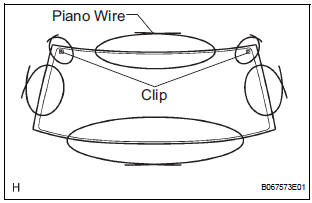
- Pass a piano wire between the body and glass from the interior.
- Tie both wire ends to wooden blocks or similar
objects.
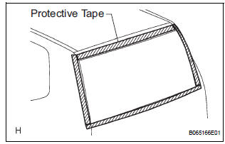
HINT: Apply protective tape to the outer surface to prevent the surface from being scratched.
NOTICE: When separating the glass, take care not to damage the paint and interior and exterior ornaments.
- Cut off the adhesive by pulling piano wire around it.
- Using a suction rubber, remove the glass.
NOTICE: Leave as much adhesive on the body as possible when removing the glass.
13. CLEAN BACK DOOR GLASS
- Clean the outer circumference of the glass white gasoline.
NOTICE:
- Do not touch the glass surface after cleaning it.
- Be careful not to damage the body.
 Back door glass
COMPONENTS
...
 Installation
1. INSTALL BACK DOOR GLASS
Clean and shape the contact surface of the vehicle
body.
Using a knife, cut away any rough adhesive on
the contact surface of the body to ensur ...
Other materials:
Lost Communication with Steering Angle Sensor
Module
DTC U0126 Lost Communication with Steering Angle Sensor
Module
DESCRIPTION
This circuit detects the angle and direction of the steering wheel and
automatically transmits a signal to
the skid control ECU and distance control ECU.
DTC No.
DTC Detection Condition
Trouble ...
Adjustment
HINT:
If the malfunction does not disappear by following the
procedure in ADJUSTMENT and the rear No. 2 seat
assembly needs to be replaced, do not disassemble the rear
No. 2 seat assembly.
1. ADJUST FRONT LEG
HINT:
Perform the following procedure if the inner leg does not
lock.
P ...
Hazard warning switch
INSPECTION
1. HAZARD WARNING SIGNAL SWITCH ASSEMBLY
Check that there is resistance between the
terminals at each switch position as shown in the
chart.
Resistance
Inspect illumination operation.
Connect the positive (+) lead from the battery
to the termina ...
