Toyota Sienna Service Manual: Removal
HINT: On the RH side, use the same procedures as on the LH side.
1. REMOVE SLIDE DOOR
- Remove the rear door scuff plate (See page IR-7).
- Remove the back door scuff plate (See page ED- 214).
- Remove the quarter trim panel (See page IR-9).
- Remove the upper rail cushion from the rail upper.
- Disconnect the 2 connectors from the body side and remove the bolt and wire.
- Open the quarter glass.
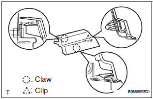
- Using a screwdriver, disengage the clip and 2 claws, remove the rail end moulding.
HINT: Tape the screwdriver tip before use.
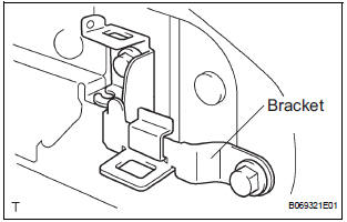
- Remove the 2 bolts and bracket center No. 2.
- Remove the 2 nuts and open stop.
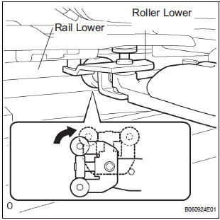
- Rotate the base of the slide door roller lower in the direction indicated by arrow in the illustration and then remove the roller from the cut area of the lower rail from the body side.
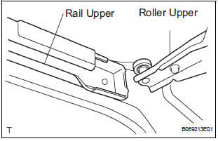
- Move the slide door rearward and then remove the slide door roller upper from the cut area in the rear part of the slide door rail upper.
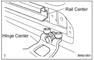
- Move the slide door further rearward and then remove the slide door hinge center from the rear part of the slide door rail center. Then, remove the slide door.
2. REMOVE SLIDE DOOR RAILS
- Remove the roof headlining (See page IR-6).
- Remove the 2 bolts, 2 nuts and the rail upper.
- Remove the 2 screws and the rear side rail.
- Remove the 3 screws and the rail center.
3. REMOVE SLIDE DOOR FULL OPEN STOP LOCK ASSEMBLY LH
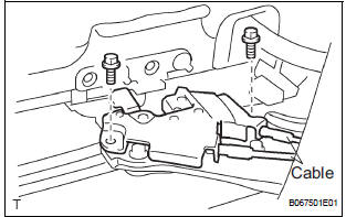
- Disconnect the 2 cables.
- Remove the 2 bolts and lock
4. REMOVE SLIDE DOOR ROLLER ASSEMBLY LOWER LH
- Remove the 3 bolts and roller.
5. REMOVE SLIDE DOOR HINGE ASSEMBLY CENTER LH
- Remove the 3 bolts and hinge.
- LH side: Remove the cover.
6. REMOVE SLIDE DOOR ROLLER ASSEMBLY UPPER
- Remove the 2 bolts and roller.
7. REPLACE SLIDE DOOR HALF OPEN STOPPER SUBASSEMBLY
- Using a screwdriver, remove the 2 clips and cover.
HINT: Tape the screwdriver tip before use.
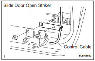
- Remove the 2 bolts and disconnect the control cable from the open striker.
- Disconnect the control cable from the half open stopper.
- Remove the 2 bolts and half open stopper.
8. REPLACE SLIDE DOOR HALF OPEN STOPPER CONTROL ASSEMBLY
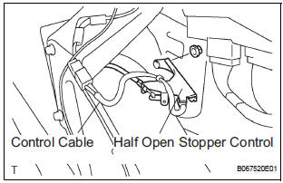
- Remove the 2 nuts and half open stopper control.
- Remove the control cable.
9. REPLACE SLIDE DOOR OPEN STRIKER LH
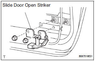
- Remove the 2 nuts and open striker.
10. REPLACE SLIDE DOOR OPEN STRIKER RH
HINT: Use the same procedures for the LH side.
11. REPLACE SLIDE DOOR OPEN STOP LH
- Remove the 2 nuts and open stop.
12. REPLACE SLIDE DOOR OPEN STOP RH
HINT: Use the same procedures for the LH side.
 Slide door
COMPONENTS
...
 Disassembly
HINT:
On the RH side, use the same procedures as on the LH side.
1. REMOVE REAR DOOR WINDOW FRAME MOULDING
REAR LH (See page ET-30)
2. REMOVE REAR DOOR WINDOW FRAME MOULDING
SUB-ASSEMBLY LH (See ...
Other materials:
Correct use of the seat belts
Extend the shoulder belt so that
it comes fully over the shoulder,
but does not come into contact
with the neck or slide off the
shoulder.
Position the lap belt as low as
possible over the hips.
Adjust the position of the seatback.
Sit up straight and well
back in the seat.
...
Open in One Side of CAN Branch Line
DESCRIPTION
If 2 or more ECUs and/or sensors do not appear on the intelligent tester
"Communication Bus Check"
screen, one side of the CAN branch wire may be open. (One side of the CAN-H
[branch wire] / CAN-L
[branch wire] of the ECU and/or sensor is open.)
Symptom
...
Reassembly
1. INSTALL REAR WHEEL CYLINDER CUP KIT
(a) Temporarily tighten the bleeder plug to the wheel
cylinder, and install the bleeder plug cap.
(b) Apply lithium soap base glycol grease to the 2 new
wheel cylinder cups and the 2 pistons.
(c) Install the 2 wheel cylinder cups to each piston.
...
