Toyota Sienna Service Manual: Removal
1. DISCONNECT CABLE FROM NEGATIVE BATTERY TERMINAL 2. DRAIN ENGINE COOLANT 3. REMOVE FRONT WIPER ARM HEAD CAP (See page WW-4) 4. REMOVE FRONT WIPER ARM RH (See page WW-4) 5. REMOVE FRONT WIPER ARM LH (See page WW-4) 6. REMOVE COWL TOP VENTILATOR LOUVER SUBASSEMBLY (See page WW-4) 7. REMOVE WINDSHIELD WIPER MOTOR AND LINK ASSEMBLY (See page WW-4) 8. REMOVE NO. 1 COWL TOP TO COWL BRACE INNER (See page FU-13) 9. REMOVE COWL TOP PANEL SUB-ASSEMBLY OUTER FRONT (See page FU-13) 10. REMOVE NO. 1 ENGINE UNDER COVER 11. REMOVE V-BANK COVER SUB-ASSEMBLY (See page EM-28) 12. REMOVE AIR CLEANER CAP SUB-ASSEMBLY (See page FU-13) 13. REMOVE INTAKE AIR SURGE TANK ASSEMBLY (See page FU-14) 14. REMOVE NO. 1 SURGE TANK STAY
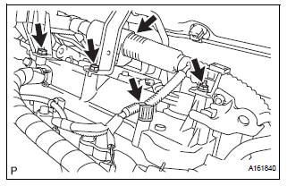
(a) Remove the 2 bolts and nut and disconnect the 2 harness clamps.
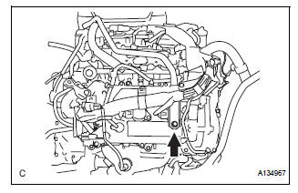
(b) Remove the bolt and No. 1 surge tank stay.
15. REMOVE IGNITION COIL ASSEMBLY
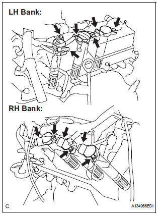
(a) Disconnect the 6 ignition coil connectors.
(b) Remove the 6 bolts and 6 ignition coils.
16. REMOVE SPARK PLUG
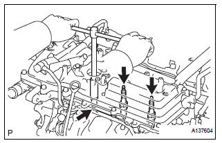
(a) Remove the 6 spark plugs.
 On-vehicle inspection
NOTICE:
In this section, the terms "cold" and "hot" refer to the
temperature of the coils. "Cold" means approximately -
10°C (14°F) to 50°C (122°F). & ...
 Installation
1. INSTALL SPARK PLUG
(a) Install the 6 spark plugs.
Torque: 18 N*m (183 kgf*cm, 13 ft.*lbf)
2. INSTALL IGNITION COIL ASSEMBLY
(a) Install the 6 ignition coils with the 6 bolts.
Torqu ...
Other materials:
Front passenger side power
window switch
Inspection
1. INSPECT POWER WINDOW REGULATOR SWITCH ASSEMBLY
Check the resistance between the switch terminals
when the switch is operated.
Standard
If the result is not as specified, replace the switch
assembly. ...
Room light assembly
ON-VEHICLE INSPECTION
1. ROOM LIGHT ASSEMBLY NO.2
Check that the resistance exists between the
terminals.
Resistance:
Below 1 Ω
2. INTERIOR DOME LIGHT SWITCH ASSEMBLY
Check that there is resistance between the
terminals at each switch position as shown in the
cha ...
Installation
HINT:
Install the RH side by the same procedure as the LH side.
1. INSTALL REAR SPEED SENSOR
(a) Clean the contacting surface of the axle hub and a
new skid control sensor.
NOTICE:
Keep the sensor rotor clean.
(b) Place the speed sensor on the axle hub so that the
connector is positioned ...
