Toyota Sienna Service Manual: Scratched / Reversed Disc
63-46 Scratched / Reversed Disc
DESCRIPTION
|
DTC No. |
DTC Detection Condition |
Trouble Area |
|
63-46 |
Scratches or dirt is found on CD surface or CD is set upside down. |
|
INSPECTION PROCEDURE
HINT: After the inspection is completed, clear the DTCs.
1 CHECK THAT CD IS INSERTED PROPERLY
- Check that the CD is not inserted upside down.
OK: CD is properly inserted.
2 CHECK DISC
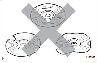
- Check that the disc is not deformed or cracked.
OK: No deformations or cracks on the disc.
3 DISC CLEANING
- Disc cleaning
- If dirt is on the disc surface, wipe it clean with a soft cloth from the inside to outside in a radial direction.
NOTICE: Do not use conventional record cleaner or antistatic preservative.
4 CLEAR DTC
- Clear the DTCs
5 RECHECK DTC
- Recheck for DTCs and check if the same trouble occurs again.
OK: Malfunction disappears
6 REPLACE DISC WITH ANOTHER AND RECHECK
- Replace the disc with another and recheck.
- Replace the disc with another normal one.
- Clear the DTCs.
- Recheck for DTCs and check if the same trouble occurs again.
OK: Malfunction disappears.
END
 Eject Error/ Elevator Error/ Clamp Error
DTC 63-45 Eject Error
DTC 63-51 Elevator Error
DTC 63-52 Clamp Error
DESCRIPTION
DTC No.
DTC Detection Condition
Trouble Area
63-45
Magazine cannot be ejec ...
 High Temperature
DTC 63-47 High Temperature
DESCRIPTION
DTC No.
DTC Detection Condition
Trouble Area
63-47
Sensor detects that CD unit temperature is high (Over
80C).
R ...
Other materials:
Reassembly
1. INSTALL GENERATOR ROTOR ASSEMBLY
(a) Place the drive end frame on the clutch pulley.
(b) Install the generator rotor assembly to the drive end
frame.
(c) Place a new generator washer on the generator
rotor.
2. INSTALL GENERATOR COIL ASSEMBLY
(a) Using a deep socket wrench (21 ...
Removal
1. Remove no. 2 Air cleaner inlet (see page em-
28)
2. Remove air cleaner cap sub-assembly
(a) Disconnect the 3 vacuum hoses.
(b) Loosen the bolt, disconnect the 2 connectors, and
remove the 2 vacuum hoses.
(c) Remove the 2 bolts, air cleaner cap sub-assembly,
and air cleaner filt ...
Diagnosis Circuit
DESCRIPTION
DTC output mode is set by connecting terminals TC and CG of the DLC3.
DTCs are displayed by blinking the SRS warning light.
HINT:
When each warning light stays blinking, a ground short in the
wiring of terminal TC of the DLC3 or an
internal ground short in each ECU is ...
