Toyota Sienna Service Manual: Shift Solenoid "D" Performance (Shift Solenoid Valve S4)

SYSTEM DESCRIPTION
The ECM uses signals from the vehicle speed sensor to detect the actual gear position (1st, 2nd, 3rd, 4th or 5th gear).
Then the ECM compares the actual gear with the shift schedule in the ECM memory
to detect mechanical
problems of the shift solenoid valves, valve body or automatic transaxle
(clutch, brake or gear etc.).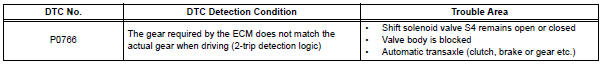
MONITOR DESCRIPTION
The ECM commands gear shifts by turning the shift solenoid valves "ON/OFF". According to the input shaft revolution, intermediate (counter) shaft revolution and output shaft revolution, the ECM detects the actual gear position (1st, 2nd, 3rd, 4th or 5th gear position). When the gear position commanded by the ECM and the actual gear position are not the same, the ECM illuminates the MIL and stores the DTC.
MONITOR STRATEGY
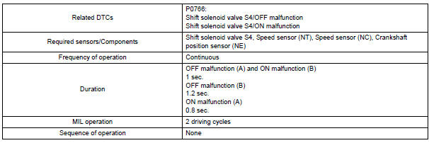
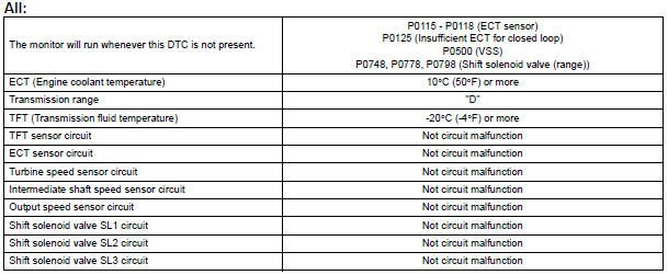
TYPICAL ENABLING CONDITIONS
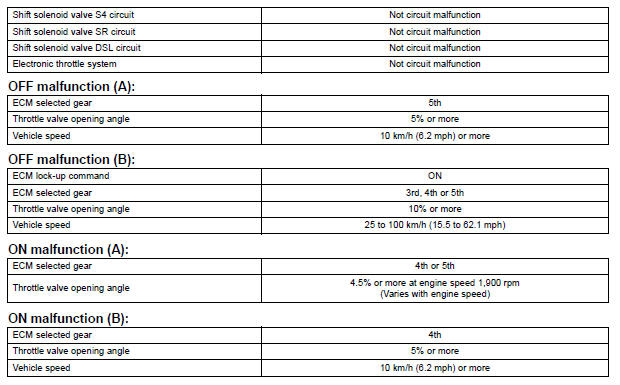
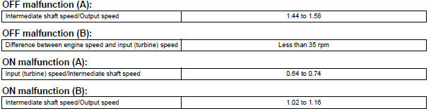
TYPICAL MALFUNCTION THRESHOLDS
Either of the following conditions is met: OFF malfunction (A) and (B), or ON malfunction (A) and (B) 2 detections are necessary per driving cycle: 1st detection; temporary flag ON 2nd detection; pending fault code ON
INSPECTION PROCEDURE
HINT: Using the intelligent tester to perform ACTIVE TEST allows relays, VSVs, actuators and other items to be operated without removing any parts. This non-intrusive functional inspection can be very useful because intermittent operation may be discovered before parts or wiring is disturbed. Performing ACTIVE TEST early in troubleshooting is one way to save diagnostic time. DATA LIST information can be displayed while performing ACTIVE TEST.
1. PERFORM ACTIVE TEST
(a) Warm up the engine.
(b) Turn the ignition switch off.
(c) Connect the intelligent tester together with the CAN VIM (controller area network vehicle interface module) to the DLC3.
(d) Turn the ignition switch to the ON position.
(e) Turn on the tester.
(f) Select the item "DIAGNOSIS / ENHANCED OBD II / ACTIVE TEST / SHIFT".
(g) According to the display on the tester, perform the "ACTIVE TEST".
HINT: While driving, the shift position can be forcibly changed with the intelligent tester.
Comparing the shift position commanded by the ACTIVE TEST with the actual shift
position enables you
to confirm the problem (See page AX-30).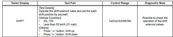
HINT:
- This test can be conducted when the vehicle speed is 50 km/h (31 mph) or less.
- The shift position commanded by the ECM is shown in the DATA LIST/SHIFT display on the intelligent tester.
1 CHECK OTHER DTCS OUTPUT (IN ADDITION TO DTC P0766)
(a) Connect the intelligent tester together with the CAN VIM (controller area network vehicle interface module) to the DLC3.
(b) Turn the ignition switch to the ON position and turn the OBD II scan tool or the intelligent tester main switch ON.
(c) Select the item "DIAGNOSIS / ENHANCED OBD II / DTC INFO / CURRENT CODES".
(d) Read the DTCs using the OBD II scan tool or the intelligent tester.
Result 
HINT: If any other codes besides "P0766" are output, perform the troubleshooting for those DTCs first.


2 INSPECT SHIFT SOLENOID VALVE S4
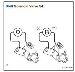
(a) Remove the shift solenoid valve S4.
(b) Measure the resistance according to the value(s) in the table below.
Standard resistance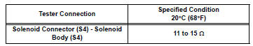
(c) Connect the positive (+) lead to the terminal of the solenoid connector, and the negative (-) lead to the solenoid body.
OK: The solenoid makes an operating sound.


3 INSPECT TRANSMISSION VALVE BODY ASSEMBLY
OK: There are no foreign objects on each valve and they operate smoothly.

4 INSPECT TORQUE CONVERTER CLUTCH ASSEMBLY
OK: The torque converter clutch operates normally.

REPAIR OR REPLACE AUTOMATIC TRANSAXLE ASSEMBLY
 Pressure Control Solenoid "A" Electrical (Shift
Solenoid Valve SL1)
Pressure Control Solenoid "A" Electrical (Shift
Solenoid Valve SL1)
DESCRIPTION
Shifting from 1st to 5th is performed in combination with "ON" and "OFF"
operation of the shift solenoid
valves SL1, SL2, SL3, S4 and SR which are controlled by ...
 Shift Solenoid "E" Performance (Shift Solenoid
Valve SR)
Shift Solenoid "E" Performance (Shift Solenoid
Valve SR)
SYSTEM DESCRIPTION
The ECM uses signals from the vehicle speed sensor to detect the actual gear
position (1st, 2nd, 3rd, 4th
or 5th gear).
Then the ECM compares the actual gear with the shi ...
Other materials:
How to proceed with
troubleshooting
HINT:
*: Use the intelligent tester.
1 VEHICLE BROUGHT TO WORKSHOP
2 CUSTOMER PROBLEM ANALYSIS
(a) Confirm problem symptoms
3 CHECK MULTIPLEX COMMUNICATION SYSTEM*
Check if the multiplex communication system DTC is output.
HINT:
The center airbag sensor assembly of this system ...
Checking monitor status
The purpose of the monitor result (mode 06) is to allow
access to the results for on-board diagnostic monitoring tests
of specific components/systems that are not continuously
monitored. Examples are catalyst, evaporative emission
(EVAP) and thermostat.
The monitor result allows the OBD II sc ...
Disposal
HINT:
Use the same procedures for the RH side and LH side.
The procedures listed below are for the LH side.
When scrapping a vehicle equipped with the SRS or
disposing of the curtain shield airbag assembly, be sure to
deploy the airbag first in accordance with the proce ...
