Toyota Sienna Service Manual: Short in Driver Side Squib 2nd Step Circuit
DTC B1180/17 Short in Driver Side Squib 2nd Step Circuit
DESCRIPTION
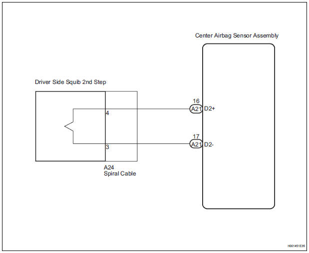
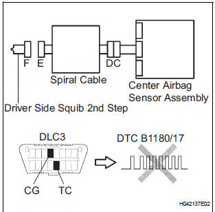
The driver side squib 2nd step circuit consists of the center airbag sensor assembly, the spiral cable and the steering pad.
The circuit instructs the SRS to deploy when deployment conditions are met.
DTC B1180/17 is recorded when a short circuit is detected in the driver side squib 2nd step circuit.
|
DTC No. |
DTC Detecting Condition |
Trouble Area |
|
B1180/17 |
|
|
WIRING DIAGRAM
INSPECTION PROCEDURE
HINT:
- Perform the simulation method by selecting the "check mode" (signal check) with the intelligent tester
- After selecting the "check mode" (signal check), perform the simulation method by wiggling each connector of the airbag system or driving the vehicle on a city or rough road
1 CHECK STEERING PAD (DRIVER SIDE SQUIB 2ND STEP)
- Turn the ignition switch to the LOCK position.
- Disconnect the negative (-) terminal cable from the battery, and wait for at least 90 seconds.
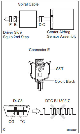
- Disconnect the connectors from the steering pad.
- Connect the white wire side of SST (resistance 2.1 Ω) to the spiral cable.
CAUTION: Never connect a tester to the steering pad (driver side squib 2nd step) for measurement, as this may lead to a serious injury due to airbag deployment.
NOTICE: Do not forcibly insert the SST into the terminals of the connector when connecting.
Insert the SST straight into the terminals of the connector.
SST 09843-18060
- Connect the negative (-) terminal cable to the battery, and wait for at least 2 seconds.
- Turn the ignition switch to the ON position, and wait for at least 60 seconds.
- Clear the DTCs stored in memory (5).
- Turn the ignition switch to the LOCK position.
- Turn the ignition switch to the ON position, and wait for at least 60 seconds.
- Check the DTCs (5).
OK: DTC B1180/17 is not output. HINT: Codes other than DTC B1180/17 may be output at this time, but they are not related to this check.
 Go to step 2

REPLACE STEERING PAD
2 CHECK CONNECTORS
- Turn the ignition switch to the LOCK position.
- Disconnect the negative (-) terminal cable from the battery, and wait for at least 90 seconds.
- Disconnect the SST (resistance 2.1 Ω) from the spiral cable.
- Check that the spiral cable connectors (on the steering pad side) are not damaged.
OK: The lock button is not disengaged, and the claw of the lock is not deformed or damaged.
 REPLACE SPIRAL CABLE

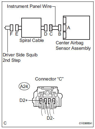
3 CHECK DRIVER SIDE SQUIB 2ND STEP CIRCUIT
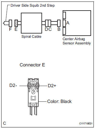
- Disconnect the connector from the center airbag sensor assembly.
- Release the activation prevention mechanism built into connector "B" (7).
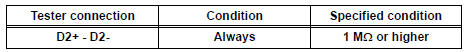
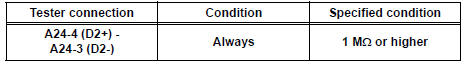
- Measure the resistance according to the value(s) in the table below.
Standard resistance
 Go to step 5

4 CHECK CENTER AIRBAG SENSOR ASSEMBLY
- Connect the connectors to the steering pad and the center airbag sensor assembly.
- Connect the negative (-) terminal cable to the battery, and wait for at least 2 seconds.
- Turn the ignition switch to the ON position, and wait for at least 60 seconds.
- Clear the DTCs stored in memory (5).
- Turn the ignition switch to the LOCK position.
- Turn the ignition switch to the ON position, and wait for at least 60 seconds.
- Check the DTCs (5).
OK: DTC B1180/17 is not output.
HINT: Codes other than DTC B1180/17 may be output at this time, but they are not related to this check.
 REPLACE CENTER AIRBAG SENSOR
ASSEMBLY
REPLACE CENTER AIRBAG SENSOR
ASSEMBLY

USE SIMULATION METHOD TO CHECK
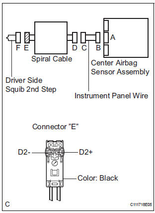
5 CHECK INSTRUMENT PANEL WIRE
- Disconnect the instrument panel wire connector from the
spiral cable.
HINT: The activation prevention mechanism of connector "B" has already been released.
- Measure the resistance according to the value(s) in the table below.
Standard resistance
 REPAIR OR REPLACE INSTRUMENT
PANEL
WIRE
REPAIR OR REPLACE INSTRUMENT
PANEL
WIRE

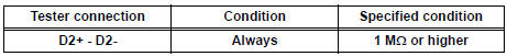
6 CHECK SPIRAL CABLE
- Release the activation prevention mechanism built into connector "D" (7).
- Measure the resistance according to the value(s) in the table below.
Standard resistance
 REPLACE SPIRAL CABLE

USE SIMULATION METHOD TO CHECK
 Short to B+ in Curtain Shield Squib LH Circuit
DTC B1168/86 Short to B+ in Curtain Shield Squib LH Circuit
DESCRIPTION
The curtain shield squib LH circuit consists of the center airbag sensor
assembly and the curtain shield
airbag assembly LH ...
 Open in Driver Side Squib 2nd Step Circuit
DTC B1181/18 Open in Driver Side Squib 2nd Step Circuit
DESCRIPTION
The driver side squib 2nd step circuit consists of the center airbag sensor
assembly, the spiral cable and
the steering pad.
...
Other materials:
Sound Signal Circuit between Radio Receiver and Television Display
Assembly
DESCRIPTION
The television display assembly sends a sound signal to the radio receiver
through this circuit.
The sound signal that has been sent is amplified by the stereo component
amplifier or radio receiver
(built-in amplifier), and then is sent to the speakers.
If there is an open or ...
Reassembly
1. INSTALL FRONT DRIVE SHAFT BEARING
(a) Using SST and a press, install a new front drive
shaft bearing.
SST 09710-30021 (09710-03141), 09527-10011
NOTICE:
Bearing should be completely installed.
2. INSTALL FRONT DRIVE SHAFT RH HOLE SNAP RING
(a) Using a snap ring expander, install a ...
Installation
1. INSTALL TRANSMISSION CONTROL CABLE ASSEMBLY
(a) Pull in the control cable to the body.
(b) Install the cable end, as shown in the illustration.
(c) When installing the transmission control cable
assembly on the shift lever plate, place the
projection of the shift cable downward to ...
