Toyota Sienna Service Manual: Short in Front Passenger Side Squib 2nd Step Circuit
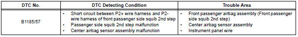
DTC B1185/57 Short in Front Passenger Side Squib 2nd Step Circuit
DESCRIPTION
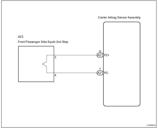
The front passenger side squib 2nd step circuit consists of the center airbag sensor assembly and the front passenger airbag assembly.
The circuit instructs the SRS to deploy when deployment conditions are met.
DTC B1185/57 is recorded when a short circuit is detected in the front passenger side squib 2nd step circuit.
WIRING DIAGRAM
INSPECTION PROCEDURE
HINT:
- Perform the simulation method by selecting the "check mode" (signal check) with the intelligent tester.
- After selecting the "check mode" (signal check), perform the simulation method by wiggling each connector of the airbag system or driving the vehicle on a city or rough road
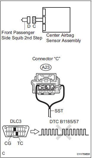
1 CHECK FRONT PASSENGER AIRBAG ASSEMBLY (FRONT PASSENGER SIDE SQUIB 2ND STEP)
- Turn the ignition switch to the LOCK position.
- Disconnect the negative (-) terminal cable from the battery, and wait for at least 90 seconds.
- Disconnect the connectors from the front passenger airbag assembly.
- Connect the black wire side of SST (resistance 2.1 Ω) to
the instrument panel wire.
CAUTION: Never connect a tester to the front passenger airbag assembly (front passenger side squib 2nd step) for measurement, as this may lead to a serious injury due to airbag deployment.
NOTICE: Do not forcibly insert the SST into the terminals of the connector when connecting.
Insert the SST straight into the terminals of the connector.
SST 09843-18060
- Connect the negative (-) terminal cable to the battery, and wait for at least 2 seconds.
- Turn the ignition switch to the ON position, and wait for at least 60 seconds.
- Clear the DTCs stored in memory.
- Turn the ignition switch to the LOCK position.
- Turn the ignition switch to the ON position, and wait for at least 60 seconds.
- Check the DTCs.
OK: DTC B1185/57 is not output.
HINT: Codes other than DTC B1185/57 may be output at this time, but they are not related to this check.
REPLACE FRONT PASSENGER AIRBAG ASSEMBLY
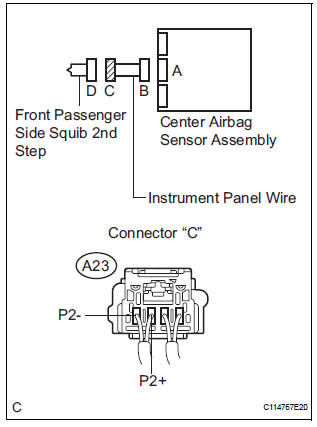
2 CHECK INSTRUMENT PANEL WIRE (FRONT PASSENGER SIDE SQUIB 2ND STEP CIRCUIT)
- Turn the ignition switch to the LOCK position.
- Disconnect the negative (-) terminal cable from the battery, and wait for at least 90 seconds.
- Disconnect the SST (resistance 2.1 Ω) from the instrument panel wire.
- Disconnect the connector from the center airbag sensor assembly.
- Release the activation prevention mechanism built into connector "B".
- Measure the resistance according to the value(s) in the table below.
Standard resistance
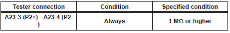
3 CHECK CENTER AIRBAG SENSOR ASSEMBLY
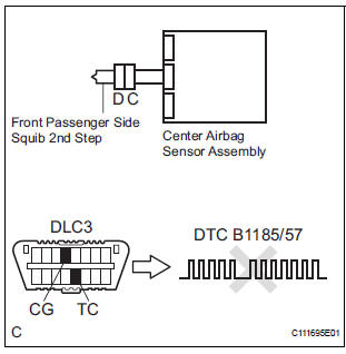
- Connect the connectors to the front passenger airbag assembly and the center airbag sensor assembly.
- Connect the negative (-) terminal cable to the battery, and wait for at least 2 seconds.
- Turn the ignition switch to the ON position, and wait for at least 60 seconds.
- Clear the DTCs stored in memory.
- Turn the ignition switch to the LOCK position.
- Turn the ignition switch to the ON position, and wait for at least 60 seconds.
- Check the DTCs.
OK: DTC B1185/57 is not output.
HINT: Codes other than DTC B1185/57 may be output at this time, but they are not related to this check.
USE SIMULATION METHOD TO CHECK
 Short to B+ in Driver Side Squib 2nd Step Circuit
DTC B1183/22 Short to B+ in Driver Side Squib 2nd Step Circuit
DESCRIPTION
The driver side squib 2nd step circuit consists of the center airbag sensor
assembly, the spiral cable and
the steering ...
 Open in Front Passenger Side Squib 2nd Step
Circuit
Open in Front Passenger Side Squib 2nd Step
Circuit
DTC B1186/58 Open in Front Passenger Side Squib 2nd Step
Circuit
DESCRIPTION
The front passenger side squib 2nd step circuit consists of the center airbag
sensor assembly and the
front passenger ...
Other materials:
If the vehicle becomes
stuck
Carry out the following procedures if the tires spin or the vehicle
becomes stuck in mud, dirt, or snow:
Stop the engine. Set the parking brake and shift the shift lever to P.
Remove the mud, snow, or sand from around the stuck tire.
Place wood, stones or some other material under the tires ...
Mirror Switch Circuit
DESCRIPTION
A switch signal of the outer mirror switch is transmitted to the
selected outer mirror control ECU by way
of the body ECU. Then, the outer mirror control ECU activates the mirror
motor to move the mirror UP,
DOWN, RIGHT and LEFT in response to the inputs.
HINT:
Th ...
Problem symptoms table
HINT:
Inspect the "Fuse" and "Relay" before confirming the
suspected area as shown in the table below.
DISPLAY FUNCTION:
SOUND FUNCTION:
REMOTE CONTROL FUNCTION:
*1: without Navigation System
*2: with Navigation System ...
