Toyota Sienna Service Manual: Short in Rear Curtain Shield Squib LH Circuit
DTC B1635/87 Short in Rear Curtain Shield Squib LH Circuit
DESCRIPTION
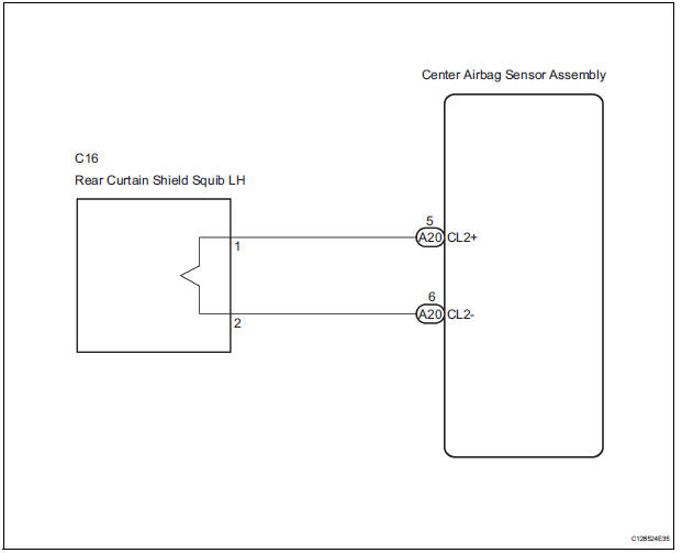
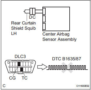
The rear curtain shield squib LH circuit consists of the center airbag sensor assembly and the curtain shield airbag assembly LH.
The circuit instructs the SRS to deploy when deployment conditions are met.
DTC B1635/87 is recorded when a short circuit is detected in the rear curtain shield squib LH circuit.
|
DTC No. |
DTC Detecting Condition |
Trouble Area |
|
B1635/87 |
|
|
WIRING DIAGRAM
INSPECTION PROCEDURE
HINT:
- Perform the simulation method by selecting the "check mode" (signal check) with the intelligent tester
- After selecting the "check mode" (signal check), perform the simulation method by wiggling each connector of the airbag system or driving the vehicle on a city or rough road
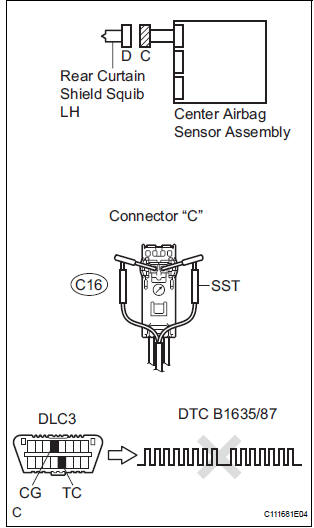
1 CHECK CURTAIN SHIELD AIRBAG ASSEMBLY LH (REAR CURTAIN SHIELD SQUIB LH)
- Turn the ignition switch to the LOCK position.
- Disconnect the negative (-) terminal cable from the battery, and wait for at least 90 seconds.
- Disconnect the connectors from the curtain shield airbag assembly LH.
- Connect the white wire side of SST (resistance 2.1 Ω) to the floor wire.
CAUTION: Never connect a tester to the curtain shield airbag assembly LH (Rear curtain shield squib LH) for measurement, as this may lead to a serious injury due to airbag deployment.
NOTICE: Do not forcibly insert the SST into the terminals of the connector when connecting.
Insert the SST straight into the terminals of the connector.
SST 09843-18060
- Connect the negative (-) terminal cable to the battery, and wait for at least 2 seconds.
- Turn the ignition switch to the ON position, and wait for at least 60 seconds.
- Clear the DTCs stored in memory (5).
- Turn the ignition switch to the LOCK position.
- Turn the ignition switch to the ON position, and wait for at least 60 seconds.
- Check the DTCs (5).
OK: DTC B1635/87 is not output. HINT: Codes other than DTC B1635/87 may be output at this time, but they are not related to this check.
 Go to step 2

REPLACE CURTAIN SHIELD AIRBAG ASSEMBLY LH
2 CHECK CONNECTORS
- Turn the ignition switch to the LOCK position.
- Disconnect the negative (-) terminal cable from the battery, and wait for at least 90 seconds.
- Disconnect the SST (resistance 2.1 Ω) from the floor wire.
- Check that the floor wire connectors (on the curtain shield airbag assembly LH side) are not damaged.
OK: The lock button is not disengaged, and the claw of the lock is not deformed or damaged.
 REPAIR OR REPLACE FLOOR WIRE

3 CHECK FLOOR WIRE (REAR CURTAIN SHIELD SQUIB LH CIRCUIT)
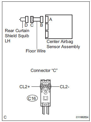
- Disconnect the connector from the center airbag sensor assembly.
- Release the activation prevention mechanism built into connector "B" (7).
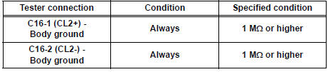
- Measure the resistance according to the value(s) in the table below.
Resistance
 REPAIR OR REPLACE FLOOR WIRE

4 CHECK CENTER AIRBAG SENSOR ASSEMBLY
- Connect the connectors to the curtain shield airbag assembly LH and the center airbag sensor assembly.
- Connect the negative (-) terminal cable to the battery, and wait for at least 2 seconds.
- Turn the ignition switch to the ON position, and wait for at least 60 seconds.
- Clear the DTCs stored in memory (5).
- Turn the ignition switch to the LOCK position.
- Turn the ignition switch to the ON position, and wait for at least 60 seconds.
- Check the DTCs (5).
OK: DTC B1635/87 is not output. HINT: Codes other than DTC B1635/87 may be output at this time, but they are not related to this check.
 REPLACE CENTER AIRBAG SENSOR
ASSEMBLY
REPLACE CENTER AIRBAG SENSOR
ASSEMBLY

USE SIMULATION METHOD TO CHECK
 Short to B+ in Rear Curtain Shield Squib RH
Circuit
Short to B+ in Rear Curtain Shield Squib RH
Circuit
DTC B1633/82 Short to B+ in Rear Curtain Shield Squib RH
Circuit
DESCRIPTION
The rear curtain shield squib RH circuit consists of the center airbag sensor
assembly and the curtain
shield airbag ...
 Open in Rear Curtain Shield Squib LH Circuit
DTC B1636/88 Open in Rear Curtain Shield Squib LH Circuit
DESCRIPTION
The rear curtain shield squib LH circuit consists of the center airbag sensor
assembly and the curtain
shield airbag assembly ...
Other materials:
Diagnosis system
1. CHECK DLC3
The vehicle's ECU uses ISO 15765-4 for
communication protocol. The terminal arrangement
of the DLC3 complies with SAE J1962 and matches
the ISO 15765-4 format.
NOTICE:
*: Before measuring the resistance, leave the
vehicle as is for at least 1 minute and do not
...
Removal
1. DISCONNECT CABLE FROM NEGATIVE BATTERY
TERMINAL
2. REMOVE FRONT BUMPER ASSEMBLY
Remove the 4 screws and separate the fender liner
from the front bumper assembly.
Remove the 8 screws and separate the engine
under cover from the front bumper assembly.
Remove the 5 ...
Removal
1. REMOVE V-BANK COVER SUB-ASSEMBLY (See
page EM-28)
2. REMOVE NO. 1 ENGINE UNDER COVER (See page
EM-26)
3. DRAIN ENGINE COOLANT (See page CO-6)
4. REMOVE NO. 2 AIR CLEANER INLET (See page EM-
28)
5. REMOVE BATTERY (See page EM-26)
6. REMOVE FRONT BUMPER ASSEMBLY (See page
ET-3)
7. REMOVE ...
