Toyota Sienna Service Manual: Short in Side Squib LH Circuit
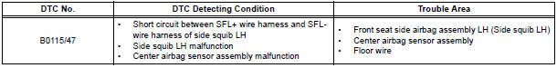
DTC B0115/47 Short in Side Squib LH Circuit
DESCRIPTION
The side squib LH circuit consists of the center airbag sensor assembly and the front seat side airbag assembly LH.
This circuit instructs the SRS to deploy when deployment conditions are met.
DTC B0115/47 is recorded when a short circuit is detected in the side squib LH circuit.
WIRING DIAGRAM
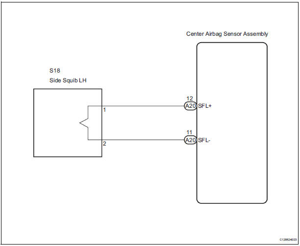
INSPECTION PROCEDURE
HINT:
- Perform the simulation method by selecting the "check mode" (signal check) with the intelligent tester
- After selecting the "check mode" (signal check), perform the simulation method by wiggling each connector of the airbag system or driving the vehicle on a city or rough road
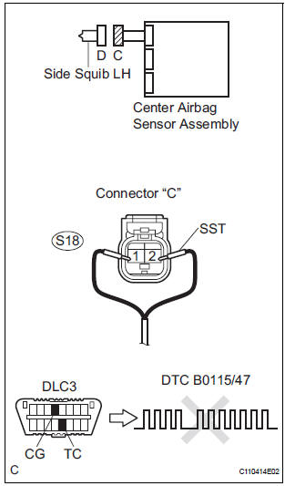
1 CHECK FRONT SEAT SIDE AIRBAG ASSEMBLY LH (SIDE SQUIB LH)
- Turn the ignition switch to the LOCK position.
- Disconnect the negative (-) terminal cable from the battery, and wait for at least 90 seconds.
- Disconnect the connectors from the front seat side airbag assembly LH.
- Connect the black wire side of SST (resistance 2.1 Ω) to the floor wire.
CAUTION: Never connect a tester to the front seat side airbag assembly LH (side squib LH) for measurement, as this may lead to a serious injury due to airbag deployment.
NOTICE: Do not forcibly insert the SST into the terminals of the connector when connecting.
Insert the SST straight into the terminals of the connector.
SST 09843-18060
- Connect the negative (-) terminal cable to the battery, and wait for at least 2 seconds.
- Turn the ignition switch to the ON position, and wait for at least 60 seconds.
- Clear the DTCs stored in memory.
- Turn the ignition switch to the LOCK position.
- Turn the ignition switch to the ON position, and wait for at least 60 seconds.
- Check the DTCs.
OK: DTC B0115/47 is not output.
HINT: Codes other than DTC B0115/47 may be output at this time, but they are not related to this check.
REPLACE FRONT SEAT ASSEMBLY LH
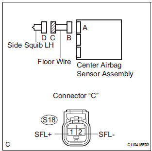
2 CHECK FLOOR WIRE (SIDE SQUIB LH CIRCUIT)
- Turn the ignition switch to the LOCK position.
- Disconnect the negative (-) terminal cable from the battery, and wait for at least 90 seconds.
- Disconnect the SST (resistance 2.1 Ω) from the floor wire.
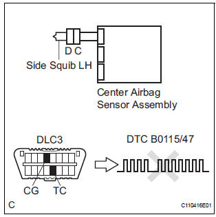
- Disconnect the connector from the center airbag sensor assembly.
- Release the activation prevention mechanism built into connector "B".
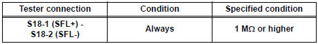
- Measure the resistance according to the value(s) in the table below.
Standard resistance
3 CHECK CENTER AIRBAG SENSOR ASSEMBLY
- Connect the connectors to the front seat side airbag assembly LH and the center airbag sensor assembly.
- Connect the negative (-) terminal cable to the battery, and wait for at least 2 seconds.
- Turn the ignition switch to the ON position, and wait for at least 60 seconds.
- Clear the DTCs stored in memory.
- Turn the ignition switch to the LOCK position.
- Turn the ignition switch to the ON position, and wait for at least 60 seconds.
- Check the DTCs.
OK: DTC B0115/47 is not output.
HINT: Codes other than code B0115/47 may be output at this time, but they are not related to this check.
USE SIMULATION METHOD TO CHECK
 USE SIMULATION METHOD TO CHECK
DTC B0113/42 Short to B+ in Side Squib RH Circuit
DESCRIPTION
The side squib RH circuit consists of the center airbag sensor assembly and
the front seat side airbag
assembly RH.
This circuit i ...
 Open in Side Squib LH Circuit
DTC B0116/48 Open in Side Squib LH Circuit
DESCRIPTION
The side squib LH circuit consists of the center airbag sensor assembly and
the front seat side assembly
LH.
This circuit instructs the S ...
Other materials:
Reassembly
1. INSTALL SEAT POSITION AIRBAG SENSOR (for Driver Seat)
2. INSTALL FRONT SEAT CUSHION SHIELD LOWER LH
Install the front seat cushion shield lower LH with
the screw.
3. INSTALL FRONT SEAT CUSHION SHIELD LOWER
RH
HINT:
Use the same procedures for the RH side and LH side.
4. INSTAL ...
Short in Driver Side Squib 2nd Step Circuit
DTC B1180/17 Short in Driver Side Squib 2nd Step Circuit
DESCRIPTION
The driver side squib 2nd step circuit consists of the center airbag sensor
assembly, the spiral cable and
the steering pad.
The circuit instructs the SRS to deploy when deployment conditions are met.
DTC B1180/17 is rec ...
Cruise Main Indicator Light Circuit
DESCRIPTION
When the cruise control main switch is on, the CRUISE main indicator light
and READY indicator light
come on. This indicates the control condition (presence or absence of a vehicle
in front, vehicle-to-vehicle
distance, and set vehicle speed) and fail-safe state through the multip ...
