Toyota Sienna Service Manual: Short to B+ in Rear Curtain Shield Squib LH Circuit
DTC B1638/86 Short to B+ in Rear Curtain Shield Squib LH Circuit
DESCRIPTION
The rear curtain shield squib LH circuit consists of the center airbag sensor assembly and the curtain shield airbag assembly LH.
The circuit instructs the SRS to deploy when deployment conditions are met.
DTC B1638/86 is recorded when a short to B+ is detected in the rear curtain shield squib LH circuit.
| DTC No. |
DTC Detecting Condition |
Trouble Area |
|
B1638/86 |
|
|
INSPECTION PROCEDURE
HINT:
- Perform the simulation method by selecting the "check mode" (signal check) with the intelligent tester (8).
- After selecting the "check mode" (signal check), perform the simulation method by wiggling each connector of the airbag system or driving the vehicle on a city or rough road
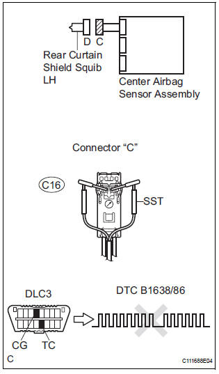
1 CHECK CURTAIN SHIELD AIRBAG ASSEMBLY LH (REAR CURTAIN SHIELD SQUIB LH)
- Turn the ignition switch to the LOCK position.
- Disconnect the negative (-) terminal cable from the battery, and wait for at least 90 seconds.
- Disconnect the connectors from the curtain shield airbag assembly LH.
- Connect the white wire side of SST (resistance 2.1 Ω) to the floor wire.
CAUTION: Never connect a tester to the curtain shield airbag assembly LH (Rear curtain shield squib LH) for measurement, as this may lead to a serious injury due to airbag deployment.
NOTICE: Do not forcibly insert the SST into the terminals of the connector when connecting.
Insert the SST straight into the terminals of the connector.
SST 09843-18060
- Connect the negative (-) terminal cable to the battery, and wait for at least 2 seconds.
- Turn the ignition switch to the ON position, and wait for at least 60 seconds.
- Clear the DTCs stored in memory (5).
- Turn the ignition switch to the LOCK position.
- Turn the ignition switch to the ON position, and wait for at least 60 seconds.
- Check the DTCs (5).
OK: DTC B1638/86 is not output. HINT: Codes other than DTC B1638/86 may be output at this time, but they are not related to this check.
 Go to step 2

REPLACE CURTAIN SHIELD AIRBAG ASSEMBLY LH
2 CHECK FLOOR WIRE (REAR CURTAIN SHIELD SQUIB LH CIRCUIT)
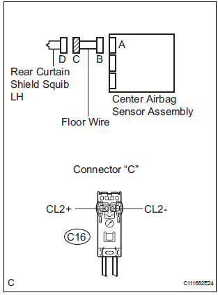
- Disconnect the connector from the center airbag sensor assembly.
- Connect the negative (-) terminal cable to the battery, and wait for at least 2 seconds.
- Turn the ignition switch to the ON position.
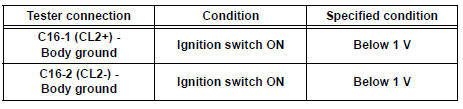
- Measure the voltage according to the value(s) in the table below.
Standard voltage
 REPAIR OR REPLACE FLOOR WIRE

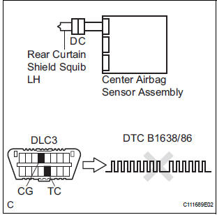
3 CHECK CENTER AIRBAG SENSOR ASSEMBLY
- Turn the ignition switch to the LOCK position.
- Disconnect the negative (-) terminal cable from the battery, and wait for at least 90 seconds.
- Connect the connectors to the curtain shield airbag assembly LH and the center airbag sensor assembly.
- Connect the negative (-) terminal cable to the battery, and wait for at least 2 seconds.
- Turn the ignition switch to the ON position, and wait for at least 60 seconds.
- Clear the DTCs stored in memory (5).
- Turn the ignition switch to the LOCK position.
- Turn the ignition switch to the ON position, and wait for at least 60 seconds.
- Check the DTCs (5).
OK: DTC B1638/86 is not output. HINT: Codes other than code B1638/86 may be output at this time, but they are not related to this check.
 REPLACE CENTER AIRBAG SENSOR
ASSEMBLY
REPLACE CENTER AIRBAG SENSOR
ASSEMBLY

USE SIMULATION METHOD TO CHECK
 Short to GND in Rear Curtain Shield Squib LH
Circuit
Short to GND in Rear Curtain Shield Squib LH
Circuit
DTC B1637/85 Short to GND in Rear Curtain Shield Squib LH
Circuit
DESCRIPTION
The rear curtain shield squib LH circuit consists of the center airbag sensor
assembly and the curtain
shield airbag ...
 SRS Warning Light Remains ON
DESCRIPTION
The SRS warning light is located on the combination meter assembly.
When the SRS is normal, the SRS warning light comes on for approximately 6
seconds after the ignition
switch is t ...
Other materials:
Ignition Coil Primary / Secondary Circuit
DTC P0351 Ignition Coil "A" Primary / Secondary Circuit
DTC P0352 Ignition Coil "B" Primary / Secondary Circuit
DTC P0353 Ignition Coil "C" Primary / Secondary Circuit
DTC P0354 Ignition Coil "D" Primary / Secondary Circuit
DTC P0355 Ignition Coil "E& ...
Installation
1. INSTALL NO.1 NAVIGATION BRACKET
Install the No.1 navigation bracket with the 4
screws.
2. INSTALL NO.2 NAVIGATION BRACKET
Install the No.2 navigation bracket with the 4
screws.
3. INSTALL INSTRUMENT CLUSTER FINISH PANEL UPPER
Install the instrum ...
Identification of noise source
1. Radio Description
Radio frequency band
Radio broadcasts use the radio frequency bands
shown in the table below.
Service area
The service areas of AM and FM broadcasts are
vastly different. Sometimes an AM broadcast
can be received very clearly ...
