Toyota Sienna Service Manual: Short to GND in Curtain Shield Squib LH Circuit
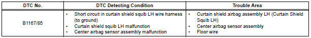
DTC B1167/85 Short to GND in Curtain Shield Squib LH Circuit
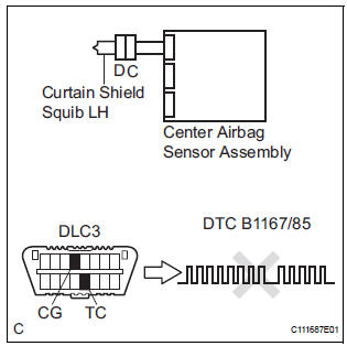
DESCRIPTION
The curtain shield squib LH circuit consists of the center airbag sensor assembly and the curtain shield airbag assembly LH.
The circuit instructs the SRS to deploy when deployment conditions are met.
DTC B1167/85 is recorded when a short to ground is detected in the curtain shield squib LH circuit.
WIRING DIAGRAM
INSPECTION PROCEDURE
HINT:
- Perform the simulation method by selecting the "check mode" (signal check) with the intelligent tester.
- After selecting the "check mode" (signal check), perform the simulation method by wiggling each connector of the airbag system or driving the vehicle on a city or rough road
1 CHECK CURTAIN SHIELD AIRBAG ASSEMBLY LH (CURTAIN SHIELD SQUIB LH)
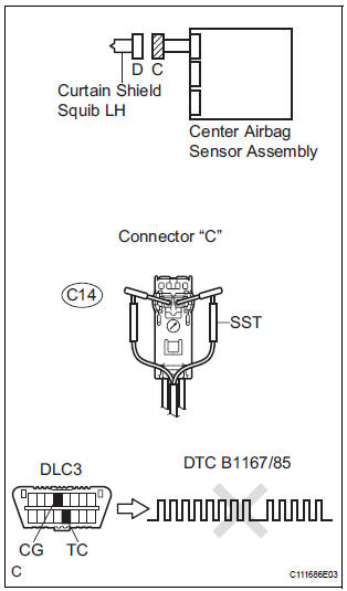
- Turn the ignition switch to the LOCK position.
- Disconnect the negative (-) terminal cable from the battery, and wait for at least 90 seconds.
- Disconnect the connectors from the curtain shield airbag assembly LH.
- Connect the white wire side of SST (resistance 2.1 Ω) to
the floor wire.
CAUTION: Never connect a tester to the curtain shield airbag assembly LH (curtain shield squib LH) for measurement, as this may lead to a serious injury due to airbag deployment.
NOTICE: Do not forcibly insert the SST into the terminals of the connector when connecting.
Insert the SST straight into the terminals of the connector.
SST 09843-18060
- Connect the negative (-) terminal cable to the battery, and wait for at least 2 seconds.
- Turn the ignition switch to the ON position, and wait for at least 60 seconds.
- Clear the DTCs stored in memory.
- Turn the ignition switch to the LOCK position.
- Turn the ignition switch to the ON position, and wait for at least 60 seconds.
- Check the DTCs
OK: DTC B1167/85 is not output.
HINT: Codes other than DTC B1167/85 may be output at this time, but they are not related to this check.
REPLACE CURTAIN SHIELD AIRBAG ASSEMBLY LH
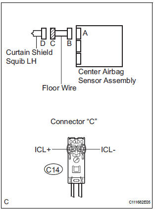
2 CHECK FLOOR WIRE (CURTAIN SHIELD SQUIB LH CIRCUIT)
- Turn the ignition switch to the LOCK position.
- Disconnect the negative (-) terminal cable from the battery, and wait for at least 90 seconds.
- Disconnect the SST (resistance 2.1 Ω) from the floor wire.
- Disconnect the connector from the center airbag sensor assembly.
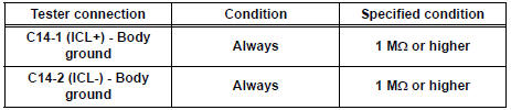
- Measure the resistance according to the value(s) in the table below.
Standard resistance
3 CHECK CENTER AIRBAG SENSOR ASSEMBLY
- Connect the connectors to the curtain shield airbag assembly LH and the center airbag sensor assembly.
- Connect the negative (-) terminal cable to the battery, and wait for at least 2 seconds.
- Turn the ignition switch to the ON position, and wait for at least 60 seconds.
- Clear the DTCs stored in memory.
- Turn the ignition switch to the LOCK position.
- Turn the ignition switch to the ON position, and wait for at least 60 seconds.
- Check the DTCs.
OK: DTC B1167/85 is not output.
HINT: Codes other than code B1167/85 may be output at this time, but they are not related to this check.
USE SIMULATION METHOD TO CHECK
 Open in Curtain Shield Squib LH Circuit
DTC B1166/88 Open in Curtain Shield Squib LH Circuit
DESCRIPTION
The curtain shield squib LH circuit consists of the center airbag sensor
assembly and the curtain shield
airbag assembly LH.
Th ...
 Short to B+ in Curtain Shield Squib LH Circuit
DTC B1168/86 Short to B+ in Curtain Shield Squib LH Circuit
DESCRIPTION
The curtain shield squib LH circuit consists of the center airbag sensor
assembly and the curtain shield
airbag assembly LH ...
Other materials:
Installation
1. INSTALL BRAKE VACUUM CHECK VALVE
ASSEMBLY
(a) Install the brake vacuum check valve assembly and
check valve grommet to the brake booster
assembly.
2. INSTALL BRAKE BOOSTER GASKET
(a) Install a new brake booster gasket to the brake
booster with master cylinder.
3. INSTALL BRAKE MASTER CYLI ...
For vehicles equipped with srs airbag and seat belt pretensioner
The SIENNA is equipped with a Supplemental Restraint System (SRS).
CAUTION: Failure to carry out the service operations in the correct sequence could cause the SRS to unexpectedly deploy during servicing and lead to serious injury. Furthermore, if a mistake is made when servicing SRS, it is poss ...
Removal
1. REMOVE NO. 1 ENGINE UNDER COVER (See page
EM-26)
2. REMOVE EXHAUST PIPE ASSEMBLY
for 2WD:(See page EX-2)
for 4WD:(See page EX-8)
3. DRAIN ENGINE COOLANT (See page CO-6)
4. DRAIN ENGINE OIL (See page LU-4)
5. REMOVE NO. 2 MANIFOLD STAY (See page EM-39)
6. REMOVE NO. 2 EXHAUST MANIFOLD HEAT ...
