Toyota Sienna Service Manual: Short to GND in Front Pretensioner Squib LH Circuit
DTC B0137/71 Short to GND in Front Pretensioner Squib LH Circuit
DESCRIPTION
The front pretensioner squib LH circuit consists of the center airbag sensor assembly and the front seat outer belt assembly LH.
This circuit instructs the SRS to deploy when deployment conditions are met.
DTC B0137/71 is recorded when a short to ground is detected in the front pretensioner squib LH circuit
|
DTC No. |
DTC Detecting Condition |
Trouble Area |
|
B0137/71 |
|
|
INSPECTION PROCEDURE
HINT:
- Perform the simulation method by selecting the "check mode" (signal check) with the intelligent tester (8).
- After selecting the "check mode" (signal check), perform the simulation method by wiggling each connector of the airbag system or driving the vehicle on a city or rough road
1 CHECK FRONT SEAT OUTER BELT ASSEMBLY LH (FRONT PRETENSIONER SQUIB LH)
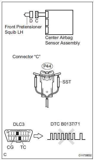
- Turn the ignition switch to the LOCK position.
- Disconnect the negative (-) terminal cable from the battery, and wait for at least 90 seconds.
- Disconnect the connectors from the front seat outer belt assembly LH.
- Connect the white wire side of SST (resistance 2.1 Ω) to the floor wire.
CAUTION: Never connect a tester to the front seat outer belt assembly LH (front pretensioner squib LH) for measurement, as this may lead to a serious injury due to airbag deployment.
NOTICE: Do not forcibly insert the SST into the terminals of the connector when connecting.
Insert the SST straight into the terminals of the connector.
SST 09843-18060
- Connect the negative (-) terminal cable to the battery, and wait for at least 2 seconds.
- Turn the ignition switch to the ON position, and wait for at least 60 seconds.
- Clear the DTCs stored in memory (5).
- Turn the ignition switch to the LOCK position.
- Turn the ignition switch to the ON position, and wait for at least 60 seconds.
- Check the DTCs (5).
OK: DTC B0137/71 is not output. HINT: Codes other than DTC B0137/71 may be output at this time, but they are not related to this check.
 Go to step 2

REPLACE FRONT SEAT OUTER BELT ASSEMBLY LH
2 FLOOR WIRE (FRONT PRETENSIONER SQUIB LH CIRCUIT)
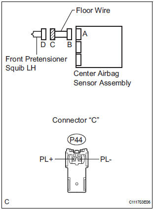
- Turn the ignition switch to the LOCK position.
- Disconnect the negative (-) terminal cable from the battery, and wait for at least 90 seconds.
- Disconnect the SST (resistance 2.1 Ω) from the floor wire.
- Disconnect the connector from the center airbag sensor assembly.
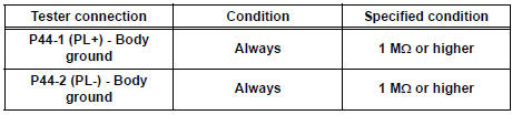
- Measure the resistance according to the value(s) in the table below.
Standard resistance
 REPAIR OR REPLACE FLOOR WIRE

3 CHECK CENTER AIRBAG SENSOR ASSEMBLY
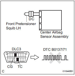
- Connect the connectors to the front seat outer belt assembly LH and the center airbag sensor assembly.
- Connect the negative (-) terminal cable to the battery, and wait for at least 2 seconds.
- Turn the ignition switch to the ON position, and wait for at least 60 seconds.
- Clear the DTCs stored in memory (5).
- Turn the ignition switch to the LOCK position.
- Turn the ignition switch to the ON position, and ait for at least 60 seconds.
- Check the DTCs (5).
OK: DTC B0137/71 is not output. HINT: Codes other than DTC B0137/71 may be output at this time, but they are not related to this check.
 REPLACE CENTER AIRBAG SENSOR
ASSEMBLY
REPLACE CENTER AIRBAG SENSOR
ASSEMBLY

USE SIMULATION METHOD TO CHECK
 Open in Front Pretensioner Squib LH Circuit
DTC B0136/74 Open in Front Pretensioner Squib LH Circuit
DESCRIPTION
The front pretensioner squib LH circuit consists of the center airbag sensor
assembly and the front seat
outer belt assembly L ...
 Short to B+ in Front Pretensioner Squib LH Circuit
DTC B0138/72 Short to B+ in Front Pretensioner Squib LH Circuit
DESCRIPTION
The front pretensioner squib LH circuit consists of the center airbag sensor
assembly and the front seat
outer belt ass ...
Other materials:
Using the rear view monitor system
Screen description
The rear view monitor system screen will be displayed if the shift
lever is shifted to R while the engine switch is in the “ON” position
(vehicles without a smart key system) or IGNITION ON mode (vehicles
with a smart key system).
Vehicle width guide line
The lin ...
Rear axle hub bolt
COMPONENTS
Replacement
HINT:
Replace the RH side using the same procedures as for the
LH side.
1. REMOVE REAR WHEEL
2. SEPARATE REAR DISC BRAKE CALIPER
ASSEMBLY LH
(a) Separate rear disc brake caliper assembly LH for
2WD and disk rear brake type (See page AH-16).
3. SEPARATE REAR D ...
Sound Signal Circuit between Radio and Navigation Assembly and
Stereo Component Amplifier
DESCRIPTION
The radio and navigation assembly sends a sound signal to the stereo
component amplifier through this
circuit.
The sound signal that has been sent is amplified by the stereo component
amplifier, and then is sent to
the speakers.
If there is an open or short in the circuit, s ...
