Toyota Sienna Service Manual: Skid Control Buzzer Circuit
DESCRIPTION
The skid control buzzer sounds and SLIP indicator blinking during VSC operation.
WIRING DIAGRAM
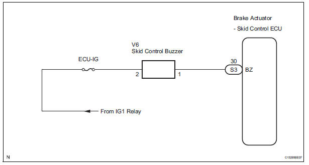
INSPECTION PROCEDURE
1 PERFORM ACTIVE TEST USING INTELLIGENT TESTER (SKID CONTROL BUZZER)
(a) Connect the intelligent tester to the DLC3.
(b) Start the engine.
(c) Select the item "VSC / BR WARN BUZ" in the ACTIVE TEST and operate the skid control buzzer on the intelligent tester.
ABS / VSC: 
(d) Check that skid control buzzer sounds by operating with the intelligent tester.
OK: The skid control buzzer sounds in accordance with operation of the intelligent tester.

REPLACE BRAKE ACTUATOR ASSEMBLY
2 INSPECT SKID CONTROL BUZZER
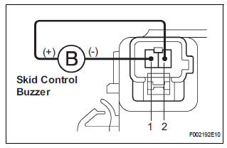
(a) Disconnect the skid control buzzer connector.
(b) Apply battery negative voltage to terminal 1, and battery positive voltage to terminal 2 of the skid control buzzer connector, and check that the buzzer sounds.
OK: The skid control buzzer sound should be heard.


3 CHECK HARNESS AND CONNECTOR (SKID CONTROL BUZZER - SKID CONTROL ECU)
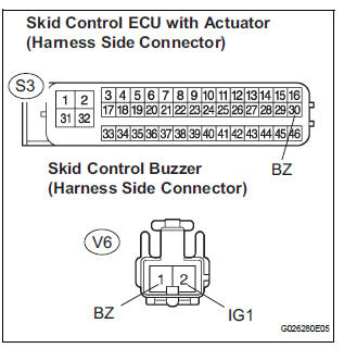
(a) Disconnect the skid control buzzer connector and the skid control ECU connector.
(b) Measure the resistance according to the value(s) in the table below.
Standard resistance 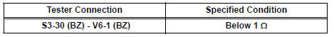
(c) Measure the resistance according to the value(s) in the table below.
Standard resistance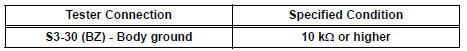
NOTICE: When replacing the brake actuator assembly, perform zero point calibration (See page BC-70)

REPLACE BRAKE ACTUATOR ASSEMBLY
 Slip Indicator Light does not Come ON
DESCRIPTION
The skid control ECU is connected to the combination meter via CAN and
multiplex communications.
The SLIP indicator blinks during VSC and/or TRAC operation.
When the system fails, ...
 TC and CG Terminal Circuit
DESCRIPTION
Connecting terminals TC and CG of the DLC3 causes the ECU to display the DTC
by blinking the ABS
warning light and/or VSC warning light.
WIRING DIAGRAM
INSPECTION PROCEDURE
NOTI ...
Other materials:
How to proceed with
troubleshooting
1 VEHICLE BROUGHT TO WORKSHOP
2 CUSTOMER PROBLEM ANALYSIS
Interview the customer and confirm the trouble.
Confirm the problem by duplicating the conditions
described by the customer
3 BASIC INSPECTION
Basic inspection.
Measure the battery voltage.
Standard voltage:
11 ...
Camshaft Position Sensor "A" Circuit
DESCRIPTION
The intake camshaft's Variable Valve Timing (VVT) sensor (G signal) consists
of a magnet and MRE
(Magneto Resistance Element).
The VVT camshaft drive gear has a sensor plate with 3 teeth on its outer
circumference. When the gear
rotates, changes occur in the air gaps betwee ...
Check for open circuit
(a) For an open circuit in the wire harness in Fig. 1, the resistance or
voltage, as described below.
(b) Check the resistance.
Check the resistance
Standard resistance (Fig. 2)
HINT:
Measure the resistance while lightly shaking the
wire harness vertically and horizontally. I ...
