Toyota Sienna Service Manual: Skid Control ECU Communication Stop Mode
DESCRIPTION
|
Detection Item |
Symptom |
Trouble Area |
| Skid Control ECU Communication Stop Mode |
|
|
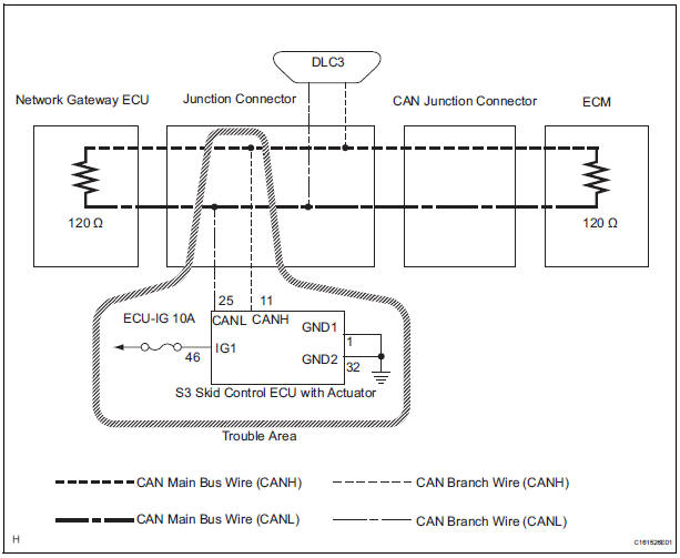
WIRING DIAGRAM
INSPECTION PROCEDURE
NOTICE:
- Turn the ignition switch off before measuring the resistances of CAN bus main wires and CAN bus branch wires.
- After the ignition switch is turned off, check that the key reminder warning system and light reminder warning system are not in operation.
- Before measuring the resistance, leave the vehicle as is for at least 1 minute and do not operate the ignition switch, any other switches, or the doors. If any doors need to be opened in order to check connectors, open the doors and leave them open.
HINT: Operating the ignition switch, any switches, or any doors triggers related ECU and sensor communication with the CAN. This communication will cause the resistance value to change.
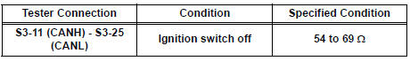
1 CHECK OPEN IN CAN BUS WIRE (SKID CONTROL ECU BRANCH WIRE)
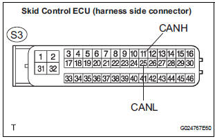
- Turn the ignition switch off.
- Disconnect the skid control ECU with Actuator connector.
- Measure the resistance according to the value(s) in the table below.
Standard resistance
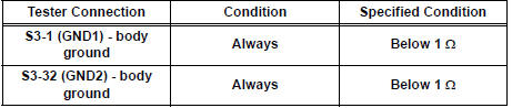
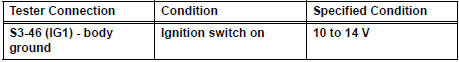
2 CHECK WIRE HARNESS (IG1, GND1, GND2)
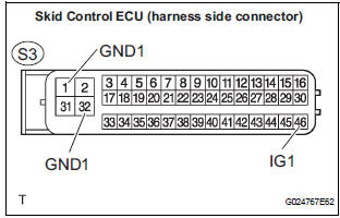
- Measure the resistance according to the value(s) in the table below.
Standard resistance
- Measure the voltage according to the value(s) in the table below.
Standard voltage
REPLACE ABS & TRACTION ACTUATOR ASSEMBLY
 Fail-safe chart
1. FAIL-SAFE FUNCTION
When communication fails in any of the main wires
(communication lines) due to a short circuit or other
causes, the fail-safe function, which is specified for
each syst ...
 Distance Control ECU Communication Stop Mode
DESCRIPTION
Detection Item
Symptom
Trouble Area
Distance Control ECU
Communication Stop
Mode
Distance control" is not displayed on the
&qu ...
Other materials:
Fold Lock Switch Circuit
DESCRIPTION
Each of the left and right seats has a fold lock switch that detects the lock
condition of the seat legs and
floor when the seat is in the stowed state. If the fold lock switch detects an
unlock condition, the 3rd SEAT
indicator on the combination meter will come on.
WIRING DIAGR ...
Front Occupant Classification Sensor LH Circuit
Malfunction
DTC B1780 Front Occupant Classification Sensor LH Circuit
Malfunction
DESCRIPTION
The front occupant classification sensor LH circuit consists of the occupant
classification ECU and the
front occupant classification sensor LH.
DTC B1780 is recorded when a malfunction is detected in the fron ...
Short in Curtain Shield Squib LH Circuit
DTC B1165/87 Short in Curtain Shield Squib LH Circuit
DESCRIPTION
The curtain shield squib LH circuit consists of the center airbag sensor
assembly and the curtain shield
airbag assembly LH.
The circuit instructs the SRS to deploy when deployment conditions are met.
DTC B1165/87 is record ...
