Toyota Sienna Service Manual: Sound Signal Circuit between Radio and Navigation Assembly and Stereo Jack Adapter
DESCRIPTION
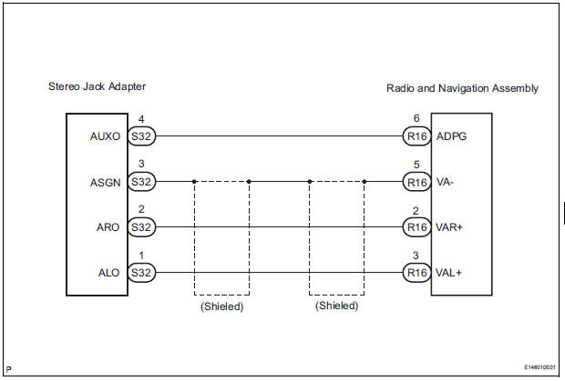
The stereo jack adapter sends an external device sound signal to the radio and navigation assembly through this circuit.
The sound signal that has been sent is amplified by the stereo component amplifier and then is sent to the speakers.
If there is an open or short in the circuit, sound cannot be heard from the speakers even if there is no malfunction in the stereo component amplifier radio and navigation assembly or speakers.
WIRING DIAGRAM
INSPECTION PROCEDURE
1 CHECK HARNESS AND CONNECTOR (RADIO AND NAVIGATION ASSEMBLY - STEREO JACK ADAPTER)
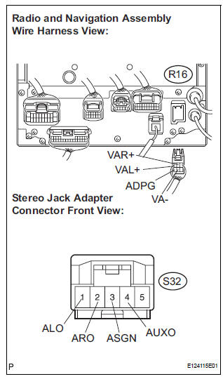
- Disconnect the connectors from the stereo jack adapter and radio and navigation assembly.
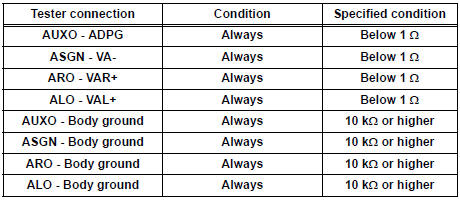
- Measure the resistance according to the value(s) in the table below.
Standard resistance
PROCEED TO NEXT CIRCUIT INSPECTION SHOWN IN PROBLEM SYMPTOMS TABLE
 Sound Signal Circuit between Radio and Navigation Assembly and
Stereo Component Amplifier
Sound Signal Circuit between Radio and Navigation Assembly and
Stereo Component Amplifier
DESCRIPTION
The radio and navigation assembly sends a sound signal to the stereo
component amplifier through this
circuit.
The sound signal that has been sent is amplified by the stereo compone ...
 Mute Signal Circuit between Radio and Navigation Assembly and
Television Display Assembly
Mute Signal Circuit between Radio and Navigation Assembly and
Television Display Assembly
DESCRIPTION
The radio and navigation assembly controls the volume according to the MUTE
signal from the television
display assembly.
The MUTE signal is sent to reduce noise and a popping sound ...
Other materials:
Route cannot be Calculated
INSPECTION PROCEDURE
1 CHECK MAP DISC
Check that the map disc is not deformed or cracked.
OK:
No deformations or cracks on map disc.
2 SET DESTINATION
Set another destination and check if the system can
calculate the route correctly.
OK:
Route can be correctly calculated.
NO ...
Diagnosis system
1. CHECK DLC3
The ECU uses ISO 15765-4 for communication.
The terminal arrangement of the DLC3 complies
with SAE J1962 and matches the ISO 15765-4
format.
NOTICE:
*: Before measuring the resistance, leave the
vehicle as is for at least 1 minute and do not
operate the ig ...
Solar Sensor Circuit (Passenger Side)
DTC B1421/21 Solar Sensor Circuit (Passenger Side)
DESCRIPTION
The solar sensor, which is installed on the upper side of the instrument
panel, detects sunlight and
controls the air conditioning in AUTO mode. The output voltage from the solar
sensor varies according to
the amount of sunli ...
