Toyota Sienna Service Manual: Sound Signal Circuit between Radio Receiver and Stereo Component Amplifier
DESCRIPTION
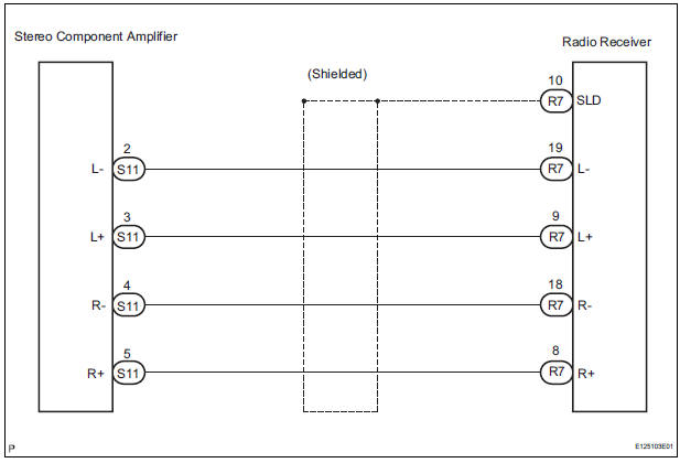
The radio receiver sends a sound signal to the stereo component amplifier through this circuit.
The sound signal that has been sent is amplified by the stereo component amplifier, and then is sent to the speakers.
If there is an open or short in the circuit, sound cannot be heard from the speakers even if there is no malfunction in the stereo component amplifier or speakers.
WIRING DIAGRAM
INSPECTION PROCEDURE
1 CHECK HARNESS AND CONNECTOR (RADIO RECEIVER - STEREO COMPONENT AMPLIFIER)
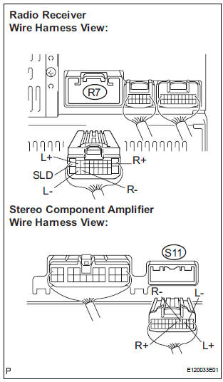
- Disconnect the connectors from the radio receiver and stereo component amplifier.
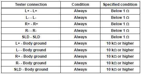
- Measure the resistance according to the value(s) in the table below.
Standard resistance
PROCEED TO NEXT CIRCUIT INSPECTION SHOWN IN PROBLEM SYMPTOMS TABLE
 Speaker Circuit
DESCRIPTION
When the vehicle has a built-in type amplifier, a sound signal is
sent from the radio receiver to the
speakers via the "6 Speaker System" circuit.
When the ...
 Sound Signal Circuit between Radio Receiver and Television Display
Assembly
Sound Signal Circuit between Radio Receiver and Television Display
Assembly
DESCRIPTION
The television display assembly sends a sound signal to the radio receiver
through this circuit.
The sound signal that has been sent is amplified by the stereo component
amplifier ...
Other materials:
On-vehicle inspection
1. INSPECT FUEL CUT RPM
(a) Increase the engine speed to at least 3500 rpm.
(b) Use a sound scope to check for injector operating
sounds.
(c) Check that when the throttle lever is released,
injector operating sounds stop momentarily (at 2500
rpm) and then resume (at 1400 rpm).
Standard
...
Terminals of ECU
1. JUNCTION CONNECTOR
Junction connector
with VSC
HINT:
*1: with Dynamic laser cruise control
without VSC
CAN junction connector (with VSC)
with VSC
The connection diagram of the components which
are connected to the CAN junction connector.
2. DLC3
...
Check mode procedure
HINT:
Intelligent tester only:
Compared to normal mode, check mode is more sensitive to
malfunctions. Therefore, check mode can detect the
malfunctions that cannot be detected by normal mode.
NOTICE:
All the stored DTCs and freeze frame data are erased if:
the ECM is changed from nor ...
