Toyota Sienna Service Manual: SRS Warning Light does not Come ON
DESCRIPTION
WIRING DIAGRAM
INSPECTION PROCEDURE
1 CHECK BATTERY
- Measure the voltage of the battery.
Standard voltage: 11 to 14 V
2 CHECK CONNECTORS
- Turn the ignition switch to the LOCK position.
- Disconnect the negative (-) terminal cable from the battery, and wait for at least 90 seconds.
- Check that the connectors are properly connected to the center airbag sensor assembly and the combination meter assembly.
OK: The connectors are properly connected.
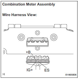
3 CHECK WIRE HARNESS (SOURCE VOLTAGE OF COMBINATION METER ASSEMBLY)
- Turn the ignition switch to the LOCK position.
- Disconnect the negative (-) terminal cable from the battery, and wait for at least 90 seconds.
- Disconnect the connector from the combination meter assembly.
- Connect the negative (-) terminal cable to the battery, and wait for at least 2 seconds.
- Turn the ignition switch to the ON position.
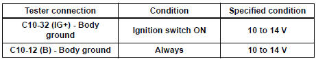
- Measure the voltage according to the value(s) in the table below.
Standard voltage
- Turn the ignition switch to the LOCK position.
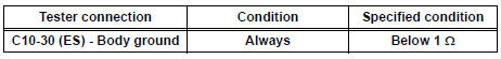
- Measure the resistance according to the value(s) in the table below.
Standard Resistance
4 CHECK SRS WARNING LIGHT
- Turn the ignition switch to the LOCK position.
- Disconnect the negative (-) terminal cable from the battery, and wait for at least 90 seconds.
- Connect the connector to the combination meter assembly.
- Disconnect the connector from the center airbag sensor assembly.
- Connect the negative (-) terminal cable to the battery, and wait for at least 2 seconds.
- Turn the ignition switch to the ON position.
- Check the SRS warning light condition.
OK: After the primary check period, SRS warning light goes off for approximately 10 seconds, and remains on.
HINT: The primary check period is approximately 6 seconds after the ignition switch is turned to the ON position.
REPLACE CENTER AIRBAG SENSOR ASSEMBLY
 SRS Warning Light Remains ON
DESCRIPTION
The SRS warning light is located on the combination meter assembly.
When the SRS is normal, the SRS warning light comes on for approximately 6
seconds after the ignition
switch is t ...
 Diagnosis Circuit
DESCRIPTION
DTC output mode is set by connecting terminals TC and CG of the DLC3.
DTCs are displayed by blinking the SRS warning light.
HINT:
When each warning light stays blinking, a g ...
Other materials:
Side Airbag Sensor Assembly RH Circuit Malfunction
DTC B1140/32 Side Airbag Sensor Assembly RH Circuit Malfunction
DESCRIPTION
The side airbag sensor RH circuit consists of the center airbag sensor
assembly and side airbag sensor
RH.
If the center airbag sensor assembly receives signals from the side airbag
sensor RH, it judges whether or
...
Transmission Range Sensor Circuit Malfunction
(PRNDL Input)
DTC P0705 Transmission Range Sensor Circuit Malfunction
(PRNDL Input)
DESCRIPTION
The park/neutral position switch detects the shift lever position and sends
signals to the ECM.
HINT:
After confirming DTC P0705, use the intelligent tester to confirm the PNP switch
signal in the ALL menu ...
Removal
1. REMOVE REAR DOOR SCUFF PLATE
2. REMOVE REAR DOOR WEATHERSTRIP
3. REMOVE BACK DOOR WEATHERSTRIP
4. REMOVE BACK DOOR SCUFF PLATE
5. REMOVE FRONT QUARTER TRIM PANEL ASSEMBLY
Remove the floor anchor cover.
Remove the bolt and disconnect the No. 2 rear seat
outer belt assem ...
