Toyota Sienna Service Manual: Starter Relay Circuit High

MONITOR DESCRIPTION
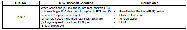
While the engine is being cranked, the positive battery voltage is applied to terminal STA of the ECM.
If the ECM detects the Starter Control (STA) signal while the vehicle is being driven, it determines that there is a malfunction in the STA circuit. The ECM then illuminates the MIL and sets the DTC.
This monitor runs when the vehicle is driven at 12.4 mph (20 km/h) for over 20 seconds.
MONITOR STRATEGY
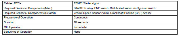
TYPICAL ENABLING CONDITIONS
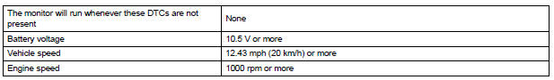
TYPICAL MALFUNCTION THRESHOLDS

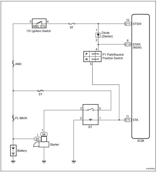
WIRING DIAGRAM
INSPECTION PROCEDURE
HINT:
- The following troubleshooting flowchart is based on the premise that the engine is cranked normally. If the engine will not crank, proceed to the problem symptoms table (See page ES-27).
- Read freeze frame data using the intelligent tester. The ECM records vehicle and driving condition information as freeze frame data the moment a DTC is stored. When troubleshooting, freeze frame data can be helpful in determining whether the vehicle was running or stopped, whether the engine was warmed up or not, whether the air-fuel ratio was lean or rich, as well as other data recorded at the time of a malfunction.
1 READ VALUE OF INTELLIGENT TESTER (STARTER SIGNAL)
(a) Connect the intelligent tester to the DLC3.
(b) Turn the ignition switch to the ON position and turn the tester on.
(c) Select the following menu items: DIAGNOSIS / ENHANCED OBD II / DATA LIST / ALL / STARTER SIG.
(d) Check the value displayed on the tester when the ignition switch is turned to the ON position and START position.
OK 

2 INSPECT PARK/NEUTRAL POSITION SWITCH
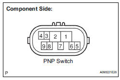
(a) Inspect the Park/Neutral Position (PNP) switch.
(1) Disconnect the P1 PNP switch connector.
(2) Measure the resistance according to the value(s) in the table below.
Standard resistance 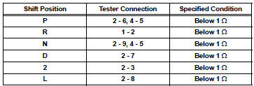
(3) Reconnect the PNP switch connector.

3 READ VALUE OF INTELLIGENT TESTER (STARTER SIGNAL)
(a) Connect the intelligent tester to the DLC3.
(b) Turn the ignition switch to the ON position and turn the tester on.
(c) Select the following menu items: DIAGNOSIS / ENHANCED OBD II / DATA LIST / ALL / STARTER SIG.
(d) Check the value displayed on the tester when the ignition switch is turned to the ON position and the START position.
OK 


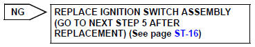
4 INSPECT IGNITION SWITCH ASSEMBLY
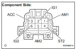
(a) Disconnect the I15 ignition switch connector.
(b) Measure the resistance according to the value(s) in the table below.
Standard resistance 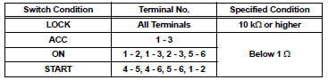
(c) Reconnect the ignition switch connector.

5 READ VALUE OF INTELLIGENT TESTER (STARTER SIGNAL)
(a) Connect the intelligent tester to the DLC3.
(b) Turn the ignition switch to the ON position and turn the tester on.
(c) Select the following menu items: DIAGNOSIS / ENHANCED OBD II / DATA LIST / PRIMARY / STARTER SIG.
(d) Check the value displayed on the tester when the ignition switch is turned to the ON position and the START position.
OK 


REPAIR OR REPLACE HARNESS OR CONNECTOR (PNP SWITCH - STA TERMINAL OF ECM)
 Control Module Performance
DESCRIPTION
The ECM continuously monitors its main and sub CPUs. This self-check ensures
that the ECM is
functioning properly. If outputs from the CPUs are different and deviate from
the sta ...
 VIN not Programmed or Mismatch - ECM / PCM
DESCRIPTION
DTC P0630 is set when the Vehicle Identification Number (VIN) is not stored
in the Engine Control Module
(ECM) or the input VIN is not accurate. Input the VIN with the intelligent ...
Other materials:
Phone screen
To display the screen shown below, press the
switch on the steering
wheel or the button.
Several functions are available to operate on each screen that is displayed
by selecting the 4 tabs.
Device name
Bluetooth® connection status
Telephone switch
Microphone
The vehicleâ ...
Problem symptoms table
SLIDING ROOF SYSTEM
Symptom
Suspected area
AUTO function does not operate
Sliding roof motor assembly
Sliding roof system does not operate
ECU-IG fuse
S/ Roof fuse
IG1 relay
Sliding roof housing assembly
Sliding roof motor switc ...
CD-ROM Abnormal
DTC 63-43 CD-ROM Abnormal
DESCRIPTION
DTC No.
DTC Detection Condition
Trouble Area
63-43
CD-ROM operation is abnormal
CD
Radio and navigation assembly
INSPECTION PROCEDURE
HINT:
After the inspection is completed, clear the DT ...
