Toyota Sienna Service Manual: Steering Angle Sensor Zero Point Malfunction
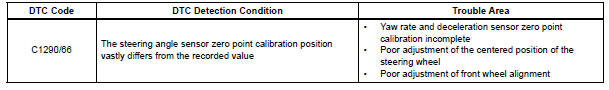
DTC C1290/66 Steering Angle Sensor Zero Point Malfunction
DESCRIPTION
The skid control ECU acquires steering angle sensor zero point every time the ignition switch is turned to the ON position and the vehicle is driven at 35 km/h (22 mph) or more for approximately 5 seconds. The ECU also stores the previous zero point.
If front wheel alignment or steering wheel position is adjusted without disconnecting the negative battery terminal, or if yaw rate and deceleration sensor zero point is not acquired after the adjustments have been completed, the skid control ECU detects the difference between the previous zero point and newly acquired zero point and outputs this DTC to indicate a poor adjustment.
Warning of the steering angle sensor zero point malfunction will be cancelled by turning the ignition switch off.
INSPECTION PROCEDURE
NOTICE: When replacing the brake actuator assembly, perform zero point calibration (See page BC-70).
1 PERFORM ZERO POINT CALIBRATION OF YAW RATE AND DECELERATION SENSOR
(a) Perform zero point calibration of the yaw rate and deceleration sensor (See page BC-70).
HINT:
- When the stored zero point of the yaw rate and deceleration sensor is erased, steering angle sensor zero point will also be erased.
- If the zero point and output value of the yaw rate and deceleration sensor and the output value of the speed sensors are not normal, steering angle sensor zero point cannot be acquired normally even if the vehicle is driven straight ahead at 35 km/h (22 mph) or more.

2 CHECK STEERING ANGLE SENSOR ZERO POINT CALIBRATION
(a) Drive the vehicle straight ahead at 35 km/h (22 mph) or more for at least 5 seconds.
(b) Check that the centered position of the steering wheel is correctly set while driving straight ahead.
HINT: If front wheel alignment and steering position are adjusted as a result of abnormal centered position of the steering wheel, acquire yaw rate and deceleration sensor zero point again after the adjustments are completed.
OK: The centered position of the steering wheel is correctly set.

3 RECONFIRM DTC
(a) Turn the ignition switch off.
(b) Clear the DTC (See page BC-82).
(c) Start the engine.
(d) Drive the vehicle and turn the steering wheel to the right and left at the speed of 35 km/h (22 mph) or more.
(e) Check if the same DTC is recorded (See page BC-82).
Result 


END
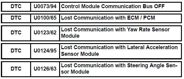
Control Module Communication Bus OFF
INSPECTION PROCEDURE
Refer to CAN communication system (See page CA-7).
 Open in Pump Motor Circuit
DTC C1251/51 Open in Pump Motor Circuit
DESCRIPTION
WIRING DIAGRAM
INSPECTION PROCEDURE
1 PERFORM ACTIVE TEST USING INTELLIGENT TESTER (ABS MOTOR RELAY)
(a) Connect the intelligent tester ...
 ABS Warning Light Remains ON
DESCRIPTION
If any of the following is detected, the ABS warning light remains on.
The skid control ECU connectors are disconnected from the skid control
ECU.
There is a malfunction in the s ...
Other materials:
Definition of terms
Terms
Definitions
Monitor Description
Description of what ECM monitors and how to detect malfunctions
(monitoring purpose and details).
Related DTCs
A group of diagnostic trouble codes that are output by ECM based on
the same malfunction detection lo ...
Reassembly
1. INSTALL POWER SLIDE DOOR TOUCH SENSOR LH
Install the touch sensor with the 4 screws.
Connect the connector.
Fix the wire harness inside the door panel with the
clip.
2. INSTALL REAR DOOR WIRE SUB-ASSEMBLY LH
Install the wire.
NOTICE:
When installing the wire, push the ...
Vehicle Speed Signal Circuit between Stereo Component Amplifier and
Combination Meter
DESCRIPTION
This circuit is necessary for the ASL (Auto Sound Leveliser) built into the
stereo component amplifier.
Speed signals are received from the combination meter and used for the ASL.
The ASL function automatically adjusts the sound data in order to enable hearing
the clear audio ...
