Toyota Sienna Service Manual: Steering Pad Switch Circuit
DESCRIPTION
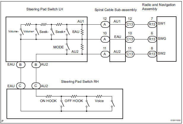
This circuit sends an operation signal from the steering pad switch to the radio receiver.
If there is an open in the circuit, the navigation system cannot be operated using the steering pad switch.
If there is a short in the circuit, the resulting condition is the same as if the switch were continuously depressed. Therefore, the radio and navigation assembly cannot be operated using the steering pad switch, and the radio and navigation assembly itself cannot function.
WIRING DIAGRAM
INSPECTION PROCEDURE
NOTICE: The vehicle is equipped with an SRS (Supplemental Restraint System) such as the airbags. Before servicing (including removal or installation of parts), be sure to read the precautionary notice for the Supplemental Restraint System (
1 INSPECT RADIO AND NAVIGATION ASSEMBLY
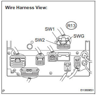
- Disconnect the radio and navigation assembly connector R13.
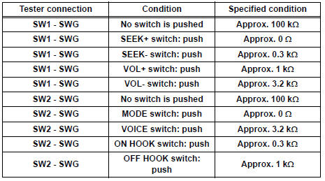
- Measure the resistance according to the value(s) in the table below.
Standard resistance
PROCEED TO NEXT CIRCUIT INSPECTION SHOWN IN PROBLEM SYMPTOMS TABLE
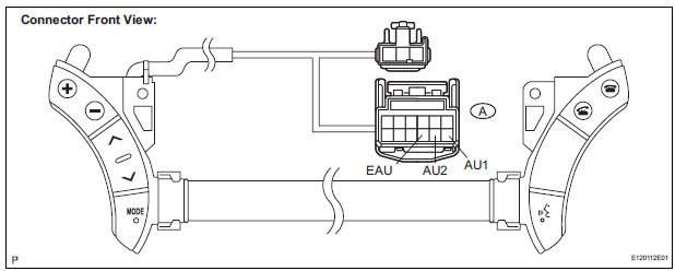
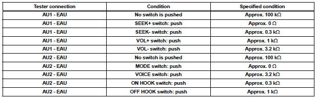
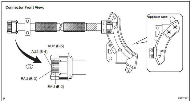
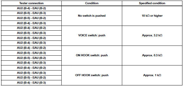
2 INSPECT STEERING PAD SWITCH ASSEMBLY
- Disconnect the steering pad switch assembly connector A.
- Measure the resistance according to the value(s) in the table below.
Standard resistance
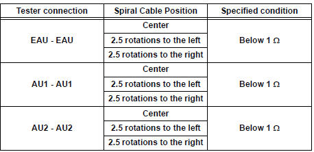
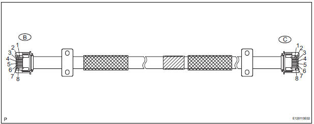
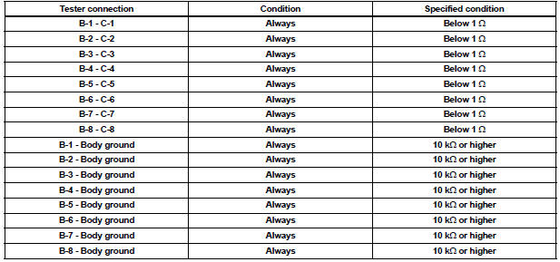
3 INSPECT SPIRAL CABLE SUB-ASSEMBLY
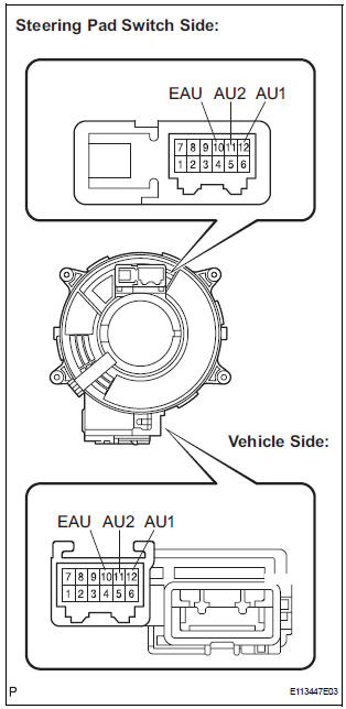
- Disconnect the steering pad switch assembly and spiral cable sub-assembly connectors.
- Measure the resistance according to the value(s) in the table below.
Standard resistance
NOTICE: The spiral cable is an important part of the SRS airbag system. Incorrect removal or installation of the spiral cable may prevent the airbag from deploying. Be sure to read the page shown in the brackets
REPAIR OR REPLACE HARNESS OR CONNECTOR (SPIRAL CABLE SUB-ASSEMBLY - RADIO AND NAVIGATION ASSEMBLY)
4 INSPECT STEERING PAD SWITCH CABLE
- Disconnect the steering pad switch LH and the steering pad switch RH.
- Measure the resistance according to the value(s) in the table below
Standard resistance
5 INSPECT STEERING PAD SWITCH RH
- Reconnect the steering pad switch RH.
- Measure the resistance according to the value(s) in the table below.
Standard resistance
REPLACE STEERING PAD SWITCH LH
 Vehicle Speed Signal Circuit between Radio and Navigation Assembly
and Combination Meter
Vehicle Speed Signal Circuit between Radio and Navigation Assembly
and Combination Meter
DESCRIPTION
The radio and navigation assembly receives a vehicle speed signal from the
combination meter and
information about the GPS antenna, and then adjusts vehicle position.
HINT:
...
 Illumination Circuit
DESCRIPTION
Power is supplied to the radio and navigation assembly and steering pad
switch illumination when the
light control switch is in the TAIL or HEAD position.
WIRING DIAGRAM
INSPECTI ...
Other materials:
Registration Complete Indication Error/ Registration Demand Transmission/
Multiple Frame Incomplete
DTC 01-E0 Registration Complete Indication Error
DTC 01-E3 Registration Demand Transmission
DTC 01-E4 Multiple Frame Incomplete
DESCRIPTION
DTC No.
DTC Detection Condition
Trouble Area
01-E0
"Registration complete" signal from the master device
c ...
Receiving a message
When an e-mail/SMS/MMS is received, the incoming message screen
pops up with sound and is ready to be operated on the screen.
Select to check the message.
Select to refuse the message.
Select to call the message
sender.
Receiving a message
Depending on the cellular phone used f ...
Black Screen
INSPECTION PROCEDURE
1 CHECK DISPLAY SETTING
Check that the display is not in "Screen OFF" mode.
OK:
The display setting is not in "Screen OFF" mode.
2 CHECK IMAGE QUALITY SETTING
Check that the screen color quality can be set.
OK:
Setting is possible.
PRESS PA ...
