Toyota Sienna Service Manual: Stereo Component Amplifier Communication Error
INSPECTION PROCEDURE
1 IDENTIFY THE COMPONENT SHOWN BY THE SUB-CODE
- Enter the diagnostic mode.
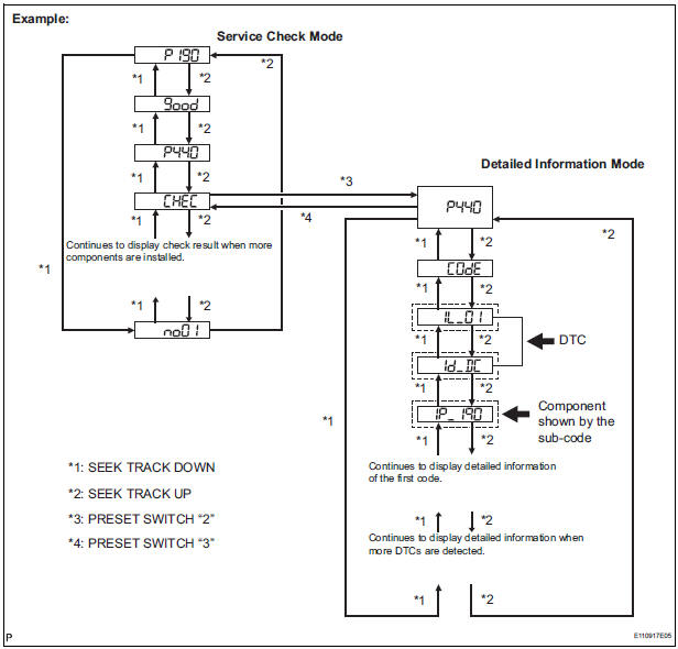
- Press the preset switch "3" to change to "Detailed Information Mode".
- Identify the component shown by the sub-code.
HINT:
- "190 (radio receiver)" is the component shown by the subcode in the example shown in the illustration.
- For details of the DTC display, refer to "DTC CHECK/ CLEAR"
2 CHECK POWER SOURCE CIRCUIT OF COMPONENT SHOWN BY SUB-CODE
- Inspect the power source circuit of the component shown
by the sub-code.
If the power source circuit is operating normally, proceed to the next step
Component Table:

3 INSPECT RADIO RECEIVER
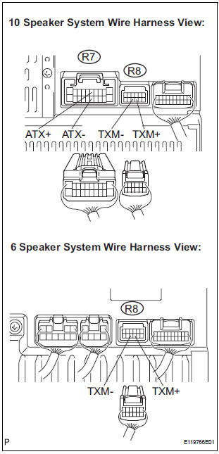
- Disconnect the radio receiver connectors.
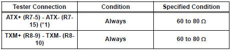
- Measure the resistance according to the value(s) in the table below.
Standard resistance
*1: 10 Speaker System
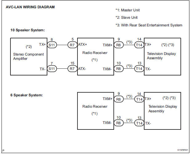
4 CHECK HARNESS AND CONNECTOR (STEREO COMPONENT AMPLIFIER -COMPONENT SHOWN BY SUB-CODE)
HINT:
- Start the check from the circuit that is near the component shown by the sub-code first.
- For details of the connectors, refer to the "TERMINALS OF ECU".
- Referring to the AVC-LAN wiring diagram below, check the AVC-LAN circuit between the stereo component amplifier and the component shown by the sub-code.
- Disconnect all connectors between the stereo component amplifier and the component shown by sub-code.
- Check for an open or short in the AVC-LAN circuit between the stereo component amplifier and the component shown by the sub-code.
OK: There is no open or short circuit.
5 REPLACE COMPONENT SHOWN BY SUB-CODE
- Replace the component shown by the sub-code with a normal one and check if the same problem occurs again.
OK: Same problem does not occur
END
 Radio Receiver Communication Error
INSPECTION PROCEDURE
1 IDENTIFY THE COMPONENT SHOWN BY THE SUB-CODE
Enter the diagnostic mode
Press the preset switch "3" to change to "Detailed
Information Mode". ...
 Television Display Assembly Communication Error
INSPECTION PROCEDURE
1 IDENTIFY THE COMPONENT SHOWN BY THE SUB-CODE
Enter the diagnostic mode.
Press the preset switch "3" to change to "Detailed
Information Mode" ...
Other materials:
Wrong Disc/ Disc cannot be Read
DTC 44-41 Wrong Disc
DTC 44-42 Disc cannot be Read
DESCRIPTION
DTC No.
DTC Detecting Condition
Trouble Area
44-41
An unsuitable disc is inserted
DVD
Television display assembly
44-42
The disc cannot be read.
IN ...
Installation
1. INSTALL ECM
Install the ECM with the 2 nuts.
Torque: 5.5 N*m (56 kgf*cm, 49 in.*lbf)
Connect the 5 ECM connectors.
2. INSTALL ECM (with 10 speakers system)
Install the ECM and stereo components amplifier
with the 4 nuts.
Torque: 5.5 N*m (56 kgf*cm, 49 ...
Reassembly
1. INSTALL IGNITION OR STARTER SWITCH
ASSEMBLY
(a) Install the ignition or starter switch assembly to the
steering column bracket assembly UPR with the 2
screws.
2. INSTALL KEY INTER LOCK SOLENOID
(a) Install the solenoid to the steering column bracket
assembly with the 2 screws.
3. INSTALL ...
