Toyota Sienna Service Manual: System Voltage
DTC P0560 System Voltage
MONITOR DESCRIPTION
The battery supplies electricity to the ECM even when the ignition switch is off. This power allows the ECM to store data such as DTC history, freeze frame data and fuel trim values. If the battery voltage falls below a minimum level, these memories are cleared and the ECM determines that there is a malfunction in the power supply circuit. When the engine is next started, the ECM illuminates the MIL and sets the DTC.
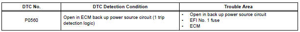
HINT: If DTC P0560 is set, the ECM does not store other DTCs.
MONITOR STRATEGY
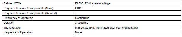
TYPICAL ENABLING CONDITIONS

TYPICAL MALFUNCTION THRESHOLDS

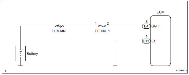
WIRING DIAGRAM
INSPECTION PROCEDURE
HINT: Read freeze frame data using the intelligent tester. The ECM records vehicle and driving condition information as freeze frame data the moment a DTC is stored. When troubleshooting, freeze frame data can be helpful in determining whether the vehicle was running or stopped, whether the engine was warmed up or not, whether the air-fuel ratio was lean or rich, as well as other data recorded at the time of a malfunction.
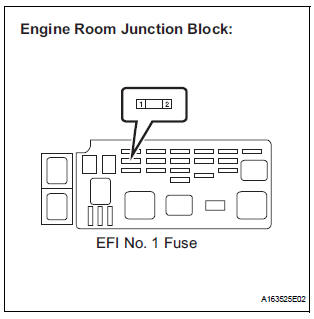
1 CHECK FUSE (EFI NO. 1 FUSE)
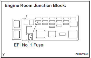
- Remove the EFI No. 1 fuse from the engine room junction block.
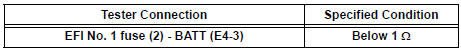
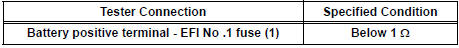
- Measure the resistance according to the value(s) in the
table below.
Standard resistance: Below 1 Ω
- Reinstall the EFI No. 1 fuse.
2 INSPECT ECM (BATT VOLTAGE)
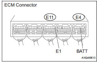
- Measure the voltage according to the value(s) in the table below.
Standard voltage
REPLACE ECM
3 CHECK HARNESS AND CONNECTOR (ECM - EFI NO. 1 FUSE)
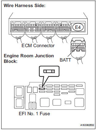
- Check the harness and the connector between the EFI No. 1 fuse and ECM.
- Remove the EFI No. 1 fuse from the engine room junction block.
- Disconnect the E4 ECM connector.
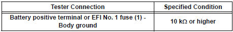
- Measure the resistance according to the value(s) in the table below.
Standard resistance : Check for open
Check for short

- Reconnect the ECM connector.
- Reinstall the EFI No. 1 fuse.
4 CHECK HARNESS AND CONNECTOR (EFI NO. 1 FUSE - BATTERY)
- Check the harness and the connector between the EFI No. 1 fuse and battery.
- Remove the EFI No. 1 fuse from the engine room junction block.
- Disconnect the negative battery cable.
- Measure the resistance according to the value(s) in the table below.
Standard resistance: Check for open
Check for short
- Reconnect the negative battery cable.
- Reinstall the EFI No. 1 fuse.
5 INSPECT BATTERY
- Check that the battery is not depleted.
CHECK AND REPLACE ENGINE ROOM RELAY BLOCK
 Cold Start Ignition Timing Performance
DTC P050B Cold Start Ignition Timing Performance
DESCRIPTION
This monitor will run when the engine is started at -10 to 50C (14 to 122F)
of the engine coolant
temperature. The DTC will set after ...
 Internal Control Module Random Access Memory
(RAM) Error
Internal Control Module Random Access Memory
(RAM) Error
DTC P0604 Internal Control Module Random Access Memory
(RAM) Error
DESCRIPTION
The ECM continuously monitors its own internal memory status, internal
circuits, and output signals
transmitted to ...
Other materials:
Rear wiper motor and bracket
COMPONENTS
REMOVAL
1. REMOVE REAR WIPER ARM
Remove the rear wiper arm head cap from the rear
wiper arm.
Remove the nut and the rear wiper arm.
2. REMOVE BACK DOOR GARNISH CENTER
3. REMOVE BACK DOOR SIDE GARNISH LH
4. REMOVE POWER BACK DOOR ROD
5. REMOVE BACK DOOR ...
Pre-collision seat belts (front seats of vehicles with pre-collision
system)
If the system determines that a collision is unavoidable, the front seat
belts will retract before the collision.
Emergency locking retractor (ELR)
The retractor will lock the belt during a sudden stop or on impact. It may
also
lock if you lean forward too quickly. A slow, easy motion wi ...
Preparation 2gr-fe engine mechanical
SST
RECOMMENDED TOOLS
EQUIPMENT
HINT:
Torx is registered trademark of Textron Inc.
SSM
...
