Toyota Sienna Service Manual: Tachometer Malfunction
DESCRIPTION
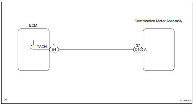
The meter CPU receives the engine revolution signal from the ECM via the direct lines. The meter CPU displays engine revolution data that is calculated based on the data received from the ECM.
WIRING DIAGRAM
INSPECTION PROCEDURE
1 PERFORM ACTIVE TEST BY INTELLIGENT TESTER
- Connect the intelligent tester to the DLC3.
- Turn the switch to the ON position.
- Turn the tester ON.
- Enter the following menus: DIAGNOSIS / OBD/MOBD / METER / ACTIVE TEST.
- Check the operation by referring to the values in the table below.
METER:

OK: Needle indication is normal.
2 READ VALUE OF INTELLIGENT TESTER (ENGINE SPEED SIGNAL)
- Connect the intelligent tester to the DLC3.
- Turn the switch to the ON position.
- Turn the tester ON.
- Enter the following menus: DIAGNOSIS / OBD/MOBD / METER / DATA LIST.
- Check the values by referring to the values in the table below
METER:

OK: Engine speed displayed on the tester is almost the same as the actual engine speed.
REPLACE COMBINATION METER ASSEMBLY
3 READ VALUE OF INTELLIGENT TESTER (ENGINE SPEED SIGNAL)
- Connect the intelligent tester to the DLC3.
- Turn the switch to the ON position.
- Turn the tester ON.
- Enter the following menus: DIAGNOSIS / OBD/MOBD / ENGINE / ACTIVE TEST.
- Check the values by referring to the values in the table below.
ENGINE:

4 CHECK HARNESS AND CONNECTOR (COMBINATION METER - ECM)
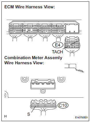
- Disconnect the E4 and C10 connectors.
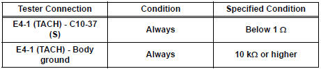
- Measure the resistance according to the value(s) in the table below.
Standard resistance
5 INSPECT COMBINATION METER ASSEMBLY
- Check the input signal waveform.
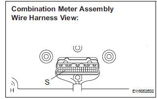
- Remove the combination meter with the connector still connected.
- Connect the oscilloscope to terminal C10-37 (S) and body ground.
- Start the engine.
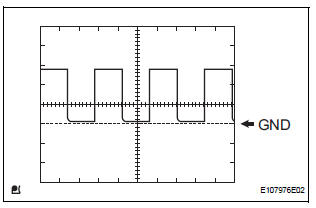
- Check the signal waveform according to the condition(s) in the table below.
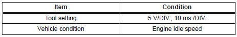
OK: The waveform is displayed as shown in the illustration
REPLACE ECM
 Speedometer Malfunction
DESCRIPTION
Factors that affect the indicated vehicle speed include tire size, tire
inflation, and tire wear. The speed indicated on the speedometer has an
allowable margin of error. This can be ...
 Fuel Receiver Gauge Malfunction
DESCRIPTION
The meter CPU uses the fuel sender gauge assembly to determine the level of
the fuel in the fuel tank.
The resistance of the fuel sender gauge will vary between approximately 15 ] ...
Other materials:
Disassembly
1. Remove repair service starter kit
(a) Remove the nut and disconnect the lead wire from
the repair service starter kit.
(b) Remove the 2 screws which are used to secure the
repair service starter kit to the repair service starter
kit.
(c) Remove the repair service starter kit.
( ...
Replacement
1. REPLACE GENERATOR DRIVE END FRAME BEARING
(a) Remove the 4 screws and retainer plate from the
drive end frame.
(b) Using SST and a hammer, tap out the drive end
frame bearing from the drive end frame.
SST 09950-60010 (09951-00250), 09950-70010
(09951-07100)
(c) Using SST and a ...
How to proceed with
troubleshooting
1 VEHICLE BROUGHT TO WORKSHOP
2 INSPECT BATTERY VOLTAGE
Standard voltage:
11 to 14 V
If the voltage is below 11 V, recharge or replace the battery
before proceeding.
3 BASIC INSPECTION
Turn the ignition switch ON.
Check whether or not the radio receiver turns on.
Result
4 CHE ...
