Toyota Sienna Service Manual: TC and CG Terminal Circuit
DESCRIPTION
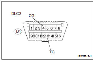
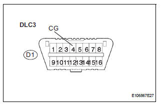
DTC output mode is set by connecting terminals TC and CG of the DLC3.
The DTCs are displayed by the blinking pattern of the ABS warning light.
WIRING DIAGRAM

HINT: When warning lights continue to blink, a ground short in the wiring of terminal TC of the DLC3 or an internal ground short in one or more ECU is suspected.
INSPECTION PROCEDURE
1 INSPECT DLC3 (BETWEEN TC of DLC3 AND CG of DLC3)
(a) Turn the ignition switch to the ON position.
(b) Measure the voltage according to the value(s) in the table below.
Standard voltage

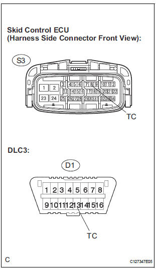
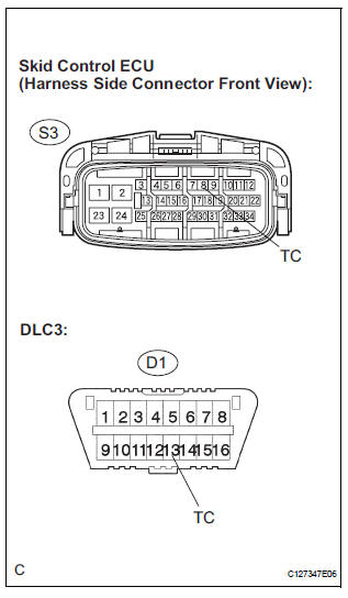
2 CHECK HARNESS AND CONNECTOR (BETWEEN SKID CONTROL ECU AND TC of DLC3)
(a) Turn the ignition switch off.
(b) Disconnect the skid control ECU connector.
(c) Measure the resistance according to the value(s) in the table below.
Standard resistance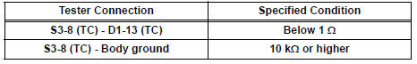
REPLACE BRAKE ACTUATOR ASSEMBLY
3 CHECK HARNESS AND CONNECTOR (BETWEEN CG of DLC3 AND BODY GROUND)
(a) Turn the ignition switch off.
(b) Measure the resistance according to the value(s) in the table below.
Standard resistance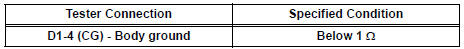

4 CHECK HARNESS AND CONNECTOR (BETWEEN SKID CONTROL ECU AND TC of DLC3)
(a) Disconnect the skid control ECU connector.
(b) Measure the resistance according to the value(s) in the table below.
Standard resistance 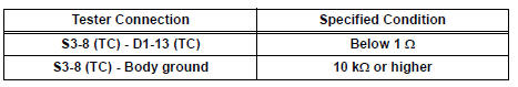

REPLACE BRAKE ACTUATOR ASSEMBLY
 Brake Warning Light does not Come ON
WIRING DIAGRAM
See page BC-52.
INSPECTION PROCEDURE
1 INSPECT BRAKE WARNING LIGHT
(a) Disconnect the skid control ECU connector.
(b) Turn the ignition switch to the on position.
(c) Check th ...
 TS and CG Terminal Circuit
DESCRIPTION
The Test Mode (signal check) circuit detects trouble in the sensor or switch
signal, which cannot be
detected by the DTC check.
Connecting terminals TS and CG of the DLC3 starts the ...
Other materials:
Installation
1. INSTALL FRONT SEAT ASSEMBLY RH
Place the seat assembly in the cabin.
NOTICE:
Be careful not to damage the body.
Connect the connectors under the seat assembly.
Tighten the 2 bolts on the front side of the seat
assembly.
Torque: 37 N*m (375 kgf*cm, 27 ft.*lbf)
...
Sound Signal Circuit between Radio Receiver and Television Display
Assembly
DESCRIPTION
The television display assembly sends a sound signal to the radio receiver
through this circuit.
The sound signal that has been sent is amplified by the stereo component
amplifier or radio receiver
(built-in amplifier), and then is sent to the speakers.
If there is an open or ...
Rear blower resistor
ON-VEHICLE INSPECTION
1. INSPECT REAR BLOWER MOTOR CONTROLLER
(a) Measure resistance according to the value(s) in the
table below..
Standard resistance
If the resistance is not as specified, replace the rear
blower motor controller.
(b) Inspect the rear blower motor controller.
(1 ...
