Toyota Sienna Service Manual: TC and CG Terminal Circuit
DESCRIPTION
Connecting terminals TC and CG of the DLC3 causes the ECU to display the DTC by blinking the ABS warning light and/or VSC warning light.
WIRING DIAGRAM
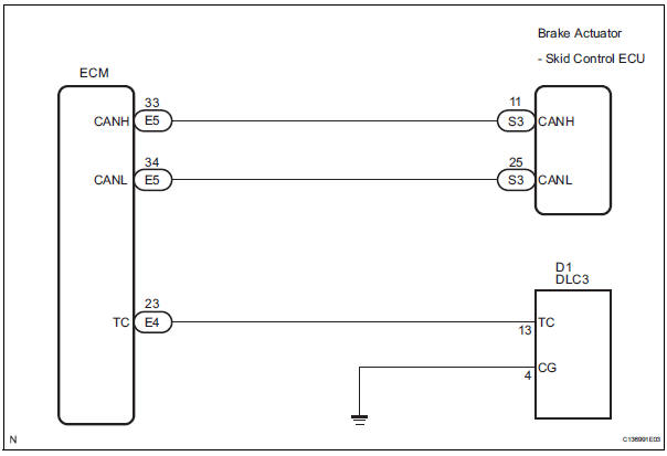
INSPECTION PROCEDURE
NOTICE: When replacing the brake actuator assembly, perform zero point calibration (See page BC-70).
1 CHECK CAN COMMUNICATION SYSTEM
(a) Check if the CAN communication system DTC is output (See page BC-82).
Result

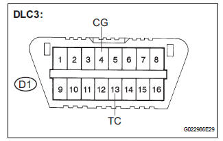
2 INSPECT DLC3
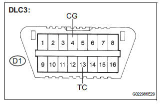
(a) Turn the ignition switch to the ON position.
(b) Measure the voltage according to the value(s) in the table below.
Standard voltage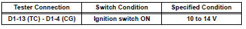
Result 


3 CHECK HARNESS AND CONNECTOR (TC of DLC3 - ECM)
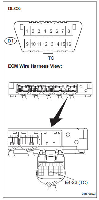
(a) Turn the ignition switch off.
(b) Disconnect the ECM connector.
(c) Measure the resistance according to the value(s) in the table below.
Standard resistance 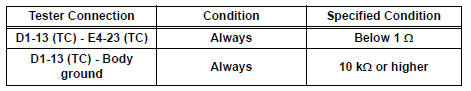

4 CHECK HARNESS AND CONNECTOR (CG of DLC3 - BODY GROUND)
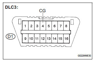
(a) Measure the resistance according to the value(s) in the table below.
Standard resistance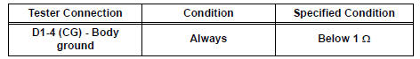

5 CHECK ECM (TC of DLC3 INPUT)
(a) Reconnect the ECM connector.
(b) Using SST, connect terminals TC and CG of the DLC3.
SST 09843-18040
(c) Turn the ignition switch to the ON position.
(d) Check that the check engine warning light is blinking.
Result 
HINT: If troubleshooting has been carried out according to the Problem Symptoms Table, refer back to the table and proceed to the next step before replacing the part (See page BC-79).

REPLACE BRAKE ACTUATOR ASSEMBLY
 Skid Control Buzzer Circuit
DESCRIPTION
The skid control buzzer sounds and SLIP indicator blinking during VSC
operation.
WIRING DIAGRAM
INSPECTION PROCEDURE
1 PERFORM ACTIVE TEST USING INTELLIGENT TESTER (SKID CONTROL ...
 TS and CG Terminal Circuit
DESCRIPTION
In the sensor check mode, a malfunction of the speed sensor that cannot be
detected when the vehicle is
stopped is detected while driving.
Transition to the sensor check mode can be ...
Other materials:
System Voltage
MONITOR DESCRIPTION
The battery supplies electricity to the ECM even when the ignition switch is
off. This power allows the
ECM to store data such as DTC history, freeze frame data and fuel trim values.
If the battery voltage falls
below a minimum level, these memories are cleared and the ...
Terminals of ecu
Check tire pressure warning ecu
HINT:
Inspect the connectors from the back side while the
connectors are connected.
(a) Disconnect the tire pressure warning antenna and
receiver connector.
(b) Measure the voltage according to the value(s) in the
table below.
(c) Connect the tire pr ...
Inspection
1. INSPECT RUNOUT OF DIFFERENTIAL RING GEAR
(a) Using a dial gauge , check the runout of the ring
gear.
Maximum runout:
0.07 mm (0.0028 in.)
If the runout is greater than the maximum, replace
the ring gear with a new one.
2. INSPECT DIFFERENTIAL RING GEAR BACKLASH
(a) Using a dial gauge, ...
