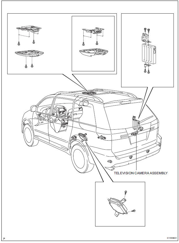
Toyota Sienna Service Manual: Television camera
COMPONENTS
REMOVAL
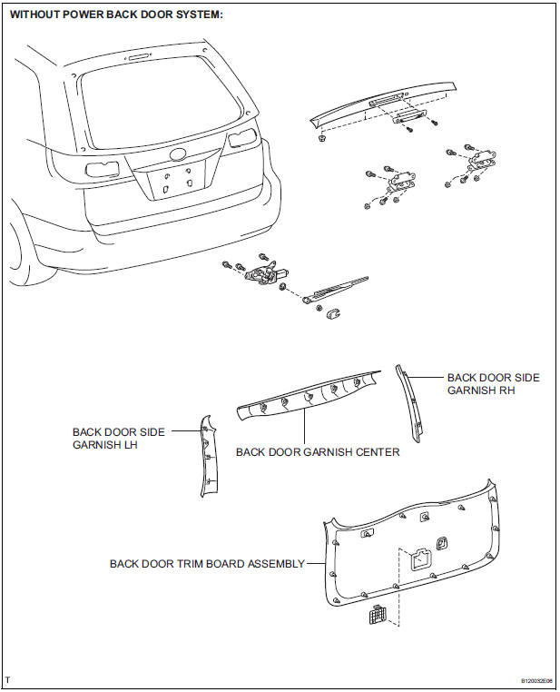
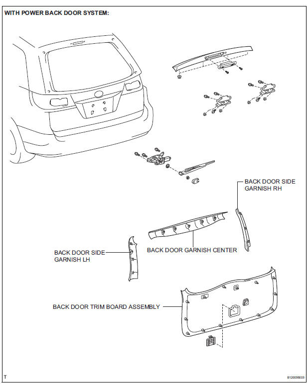
1. REMOVE BACK DOOR GARNISH CENTER
HINT:
- Back Door:
- Power Back Door:
2. REMOVE BACK DOOR SIDE GARNISH LH
HINT:
- Back Door:
- Power Back Door:
3. REMOVE BACK DOOR SIDE GARNISH RH
- Back Door:
- Power Back Door:
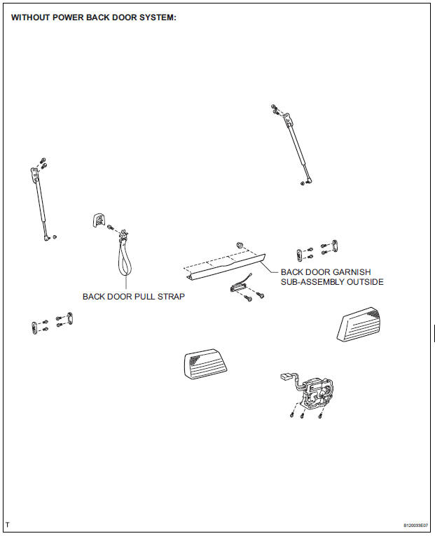
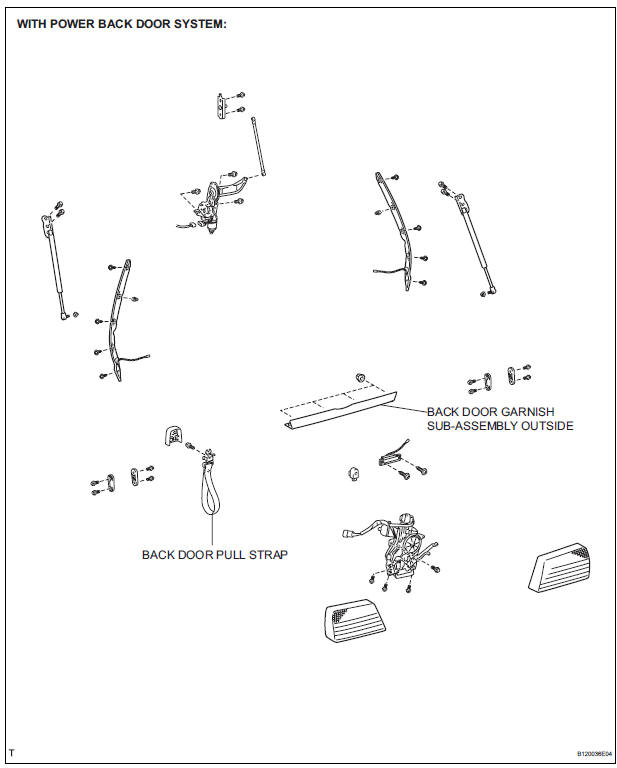
4. REMOVE BACK DOOR PULL STRAP
- Back Door:
- Power Back Door:
5. REMOVE BACK DOOR TRIM BOARD ASSEMBLY
- Back Door:
- Power Back Door:
6. REMOVE BACK DOOR GARNISH SUB-ASSEMBLY OUTSIDE
- Back Door:
- Power Back Door:
7. REMOVE TELEVISION CAMERA ASSEMBLY
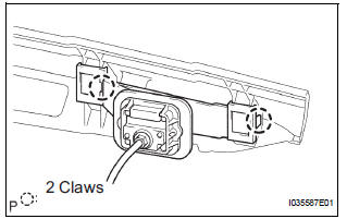
- Release the 2 claw fittings and remove the television camera assembly.
INSTALLATION
1. INSTALL TELEVISION CAMERA ASSEMBLY
2. INSTALL BACK DOOR GARNISH SUB-ASSEMBLY OUTSIDE
3. INSTALL BACK DOOR TRIM BOARD ASSEMBLY
4. INSTALL BACK DOOR PULL STRAP
HINT:
- Back Door:
- Power Back Door:
5. INSTALL BACK DOOR SIDE GARNISH RH
6. INSTALL BACK DOOR SIDE GARNISH LH
7. INSTALL BACK DOOR GARNISH CENTER
 No. 2 Ultrasonic sensor
COMPONENTS
REMOVAL
1. REMOVE REAR BUMPER COVER (2)
2. REMOVE NO. 1 ULTRASONIC SENSOR RETAINER
Remove the No. 1 ultrasonic sensor retainer as
shown in the illustration
3. REMO ...

Other materials:
Removal
1. DISCONNECT CABLE FROM NEGATIVE BATTERY
TERMINAL
2. REMOVE HEATED OXYGEN SENSOR (for Bank 1
Sensor 2) (See page EC-38)
3. REMOVE TAIL EXHAUST PIPE ASSEMBLY
(a) Remove the 2 bolts.
(b) Disconnect the 4 exhaust pipe supports and remove
the tail exhaust pipe assembly.
(c) Remove the gas ...
System description
1. DESCRIPTION OF OCCUPANT CLASSIFICATION SYSTEM
GENERAL DESCRIPTION.
In the occupant classification system, the
occupant classification ECU calculates the
weight of the occupant based on a signal from
the occupant classification sensors. This system
recognizes the occu ...
Rear Air Conditioning Relay Circuit
DESCRIPTION
The RR A/C relay is switched on by signals from the A/C amplifier. It
supplies power to the rear blower
motor.
WIRING DIAGRAM
INSPECTION PROCEDURE
1 INSPECT RELAY (RR A/C)
(a) Remove the RR A/C relay from the No. 3 relay block.
(b) Measure the resistance according to t ...
