Toyota Sienna Service Manual: Television Display Assembly Communication Error
INSPECTION PROCEDURE
1 IDENTIFY THE COMPONENT SHOWN BY THE SUB-CODE
- Enter the diagnostic mode.
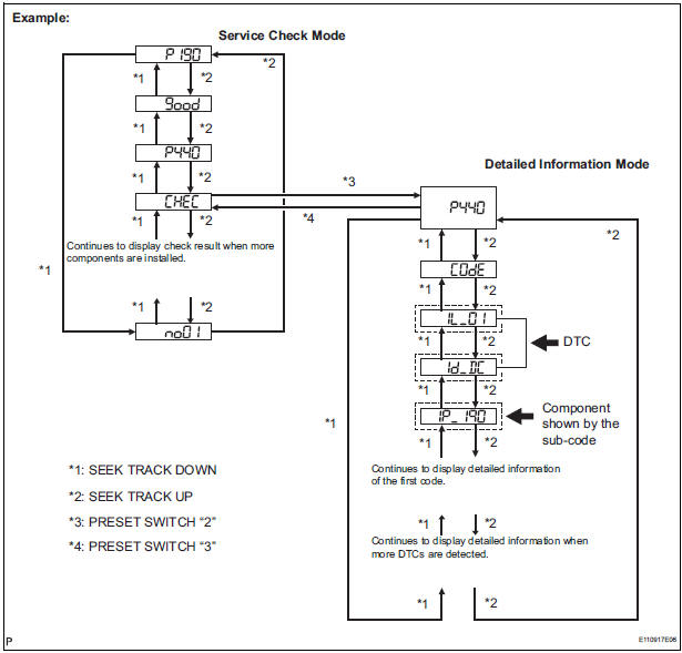
- Press the preset switch "3" to change to "Detailed Information Mode".
- Identify the component shown by the sub-code.
HINT:
- "190 (radio receiver)" is the component shown by the sub-code in the example shown in the illustration.
- For details of the DTC display, refer to "DTC CHECK/ CLEAR"
2 CHECK POWER SOURCE CIRCUIT OF COMPONENT SHOWN BY SUB-CODE
- Inspect the power source circuit of the component shown
by the sub-code.
If the power source circuit is operating normally, proceed to the next step
Component Table:

3 INSPECT RADIO RECEIVER
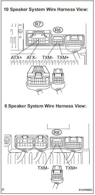
- Disconnect the radio receiver connectors.
- Measure the resistance according to the value(s) in the table below.
Standard resistance
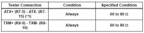
*1: 10 Speaker System
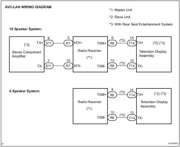
4 CHECK HARNESS AND CONNECTOR (TELEVISION DISPLAY ASSEMBLY - COMPONENT SHOWN BY SUB-CODE)
HINT:
- Start the check from the circuit that is near the component shown by the sub-code first.
- For details of the connectors, refer to "TERMINALS OF ECU".
- Referring to the AVC-LAN wiring diagram below, check the AVC-LAN circuit between the television display assembly and the component shown by the sub-code.
- Disconnect all connectors between the television display assembly and the component shown by sub-code.
- Check for an open or short in the AVC-LAN circuit between the television display assembly and the component shown by the sub-code.
OK: There is no open or short circuit
5 REPLACE COMPONENT SHOWN BY SUB-CODE
- Replace the component shown by the sub-code with a normal one and check if the same problem occurs again.
OK: Same problem does not occur.
END
 Stereo Component Amplifier Communication Error
INSPECTION PROCEDURE
1 IDENTIFY THE COMPONENT SHOWN BY THE SUB-CODE
Enter the diagnostic mode.
Press the preset switch "3" to change to "Detailed
Information Mode" ...
 Radio Receiver Power Source Circuit
DESCRIPTION
This circuit provides power to the radio receiver.
WIRING DIAGRAM
INSPECTION PROCEDURE
1 INSPECT RADIO RECEIVER ASSEMBLY
Disconnect the radio receiver connector.
Measure ...
Other materials:
EVAP System
RELATED DTCS
If any EVAP system DTCs are set, the malfunctioning area can be determined
using the table below.
NOTICE:
If the 0.02 inch reference pressure difference between the first and second
checks is greater than
the specification, the DTCs corresponding to the reference pressur ...
Clearance Warning ECU Power Source Circuit
DESCRIPTION
This circuit provides power to the clearance warning ECU.
WIRING DIAGRAM
INSPECTION PROCEDURE
1 CHECK HARNESS AND CONNECTOR (CLEARANCE WARNING ECU - AIR CONDITIONER
AMPLIFIER)
Disconnect the connectors from the clearance warning
ECU C9 and air conditioner amplifier con ...
Axle
SST
RECOMMENDED TOOLS
HINT:
Trox is a registered trademark of Trxtron Inc.
EQUIPMENT
...
