Toyota Sienna Service Manual: Terminals of ecm
Sfi system
Hint:
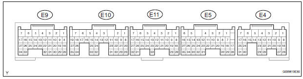
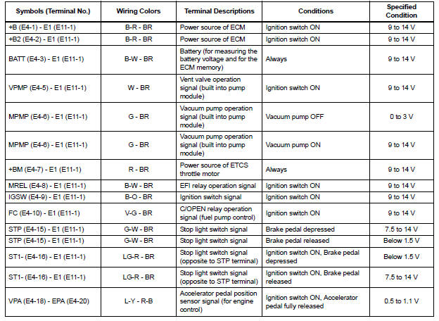
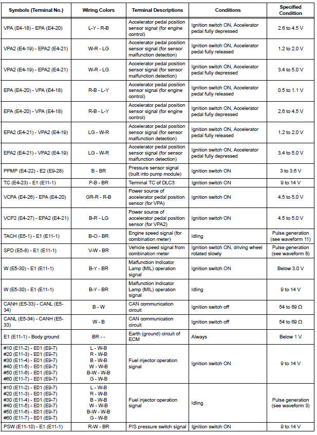
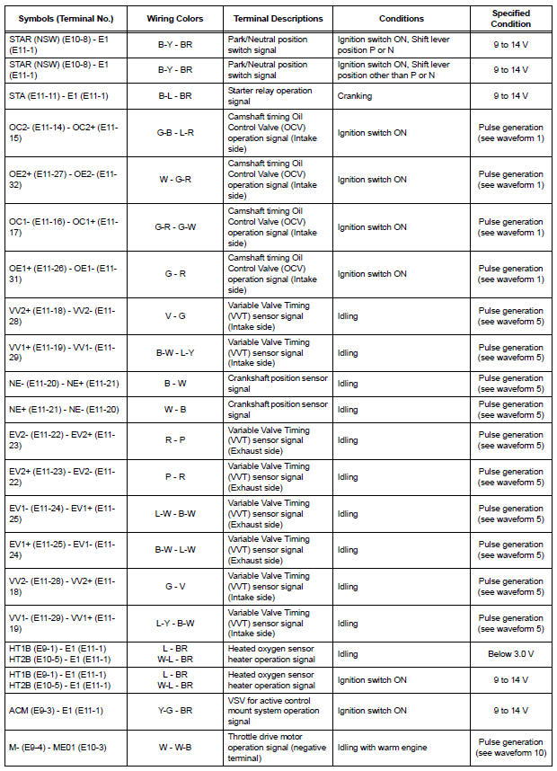
The standard normal voltage between each pair of the ECM terminals is shown in the table below. The appropriate conditions for checking each pair of the terminals are also indicated.
The check results should be compared with the standard normal voltage for that pair of terminals, listed in the "Specified Condition" column.
The illustration above can be used as a reference to identify the ECM terminal locations.
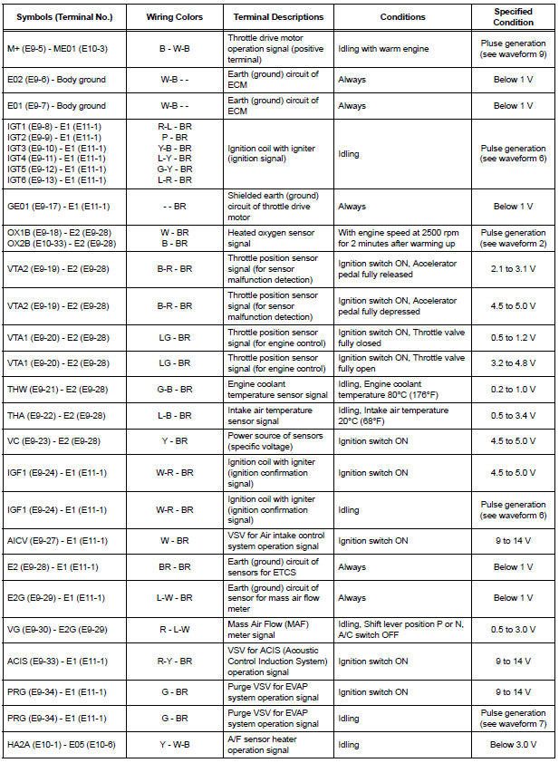
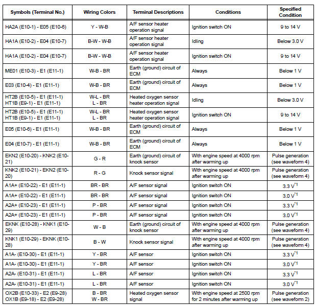
*1: The ECM terminal voltage is constant regardless of the output voltage from the sensor.
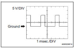
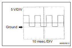
(a) WAVEFORM 1
(1) Camshaft Timing Oil Control Valve (OCV)
operation signal
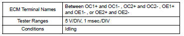
HINT:
The wavelength becomes shorter as the engine rpm increases.
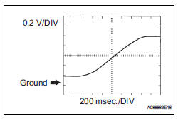
(b) WAVEFORM 2
(1) Heated oxygen sensor signal
HINT:
In the DATA LIST, item O2S B1S2 shows the ECM input values from the heated oxygen sensor.
(c) WAVEFORM 3
(1) Fuel injector operation signal
HINT:
The wavelength becomes shorter as the engine rpm increases.
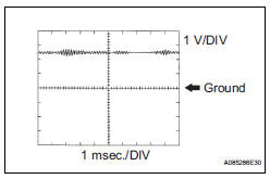
(d) WAVEFORM 4
(1) Knock sensor signal
HINT:
- The wavelength becomes shorter as the engine rpm increases.
- The waveforms and amplitudes displayed differ slightly depending on the vehicle.
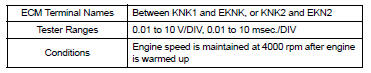
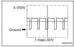
(e) WAVEFORM 5
(1) Variable Valve Timing (VVT) sensor signal (1)
(2) Crankshaft position sensor signal (2)
HINT:
The wavelength becomes shorter as the engine rpm increases.
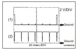
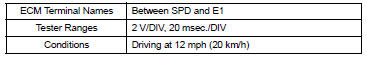
(f) WAVEFORM 6
(1) Igniter IGT signal (from ECM to igniter) (1)
(2) Igniter IGF signal (from igniter to ECM) (2)
HINT:
The wavelength becomes shorter as the engine rpm increases.
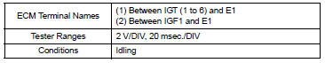
(g) WAVEFORM 7
(1) Purge VSV for EVAP system operation signal
HINT:
If the waveform is not similar to that shown in the illustration, check the waveform again after idling for 10 minutes or more.
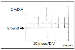
(h) WAVEFORM 8
(1) Vehicle speed signal
HINT:
- The wavelength becomes shorter as the vehicle speed increases.
- Depending on the vehicle, the output waveform voltage may rise to 12 V if influenced by optionally installed systems.
(i) WAVEFORM 9
(1) Throttle drive motor operation signal (positive
terminal) 
HINT:
The duty ratio varies depending on the throttle actuator operation.
(j) WAVEFORM 10
(1) Throttle drive motor operation signal (negative
terminal) 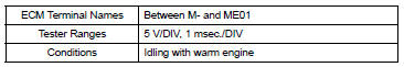
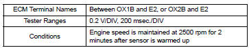
(k) WAVEFORM 11
1) Engine speed signal
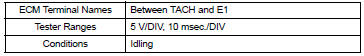
HINT:
The wavelength becomes shorter as the engine rpm increases.
 Problem symptoms table
HINT:
When a malfunction is not confirmed by a DTC (Diagnostic
Trouble Code) check and the cause of problem cannot be
identified through a basic inspection, troubleshoot according
to the priority ...
 Diagnosis system
DESCRIPTION
(a) When troubleshooting OBD II (On-Board
Diagnostics) vehicles, an intelligent tester
(complying with SAE J1987) must be connected to
the DLC3 (Data Link Connector 3) of the vehicle.
...
Other materials:
Speed sensor check (when using sst check wire)
(a) Check the speed sensor signal.
(1) Drive the vehicle straight forward. Drive the
vehicle at a speed of 45 km/h (28 mph) or higher
for several seconds and check that the ABS
warning light goes off.
HINT:
The signal check may not be completed if the
vehicle has its wheels spun or the stee ...
Precaution
Keep in mind the following points when inspecting the
dynamic laser cruise control system.
As there is a limitation on the vehicle-to-vehicle distance
controlling capability, do not overly rely on the dynamic
laser cruise control system.
Do not neglect to pay constant attentio ...
DTC check / clear
NOTICE:
All the stored DTCs and freeze frame data are erased if:
the ECM is changed from normal mode to check mode
or vice versa; or 2) the ignition switch is turned from ON
to ACC or off while in check mode.
Before changing modes, always check and make a note
of any DTCs and fr ...
