Toyota Sienna Service Manual: Terminals of ECU
1. CHECK TRANSPONDER KEY AMPLIFIER

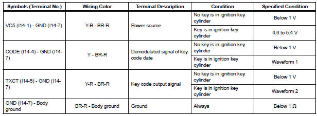
- Disconnect the I14 amplifier connector and measure the resistance between the terminal of the wire harness side connector and body ground.

If the result is not as specified, there may be a malfunction on the wire harness side.
- Reconnect the I14 amplifier connector and measure the resistance and voltage of each terminal of the connector
If the result is not as specified, the amplifier may have a malfunction.
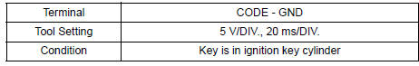
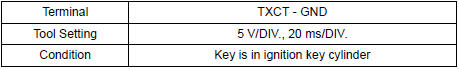
- Inspect using an oscilloscope.
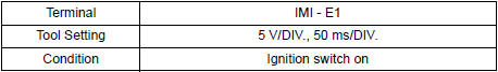
- Waveform 1 (Reference):
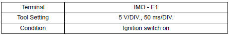
- Waveform 2 (Reference):
2. CHECK TRANSPONDER KEY ECU ASSEMBLY
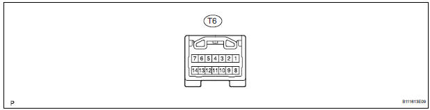
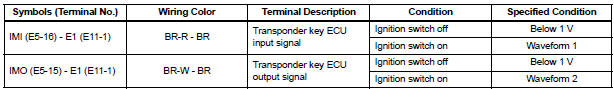
- Disconnect the T6 ECU connector and measure the resistance and voltage between each terminal of the wire harness side connector
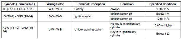
If the result is not as specified, there may be a malfunction on the wire harness side.
- Reconnect the T9 ECU connector and measure the voltage of each terminal of the connector.
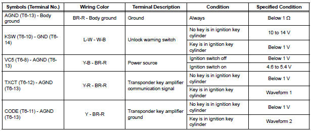
If the result is not as specified, the ECU may have a malfunction.
- Inspect using an oscilloscope.
- Wave form 1 (Reference):
- Wave form 2 (Reference):
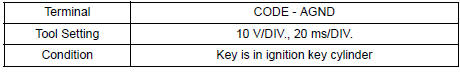
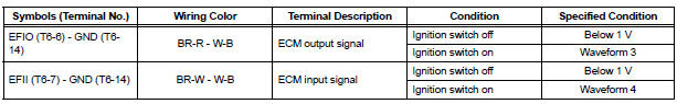
- Wave form 3 (Reference):
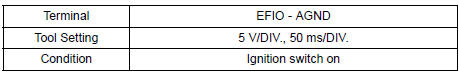
- Wave form 4 (Reference):
3. CHECK ECM
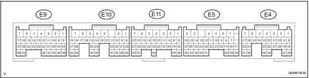
- Disconnect the E11 ECM connector and measure the resistance between the terminal of the wire harness side connector and body ground.

If the result is not as specified, there may be a malfunction on the wire harness side.
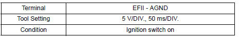
- Reconnect the E11 ECM. Measure the voltage between each terminal of the connector according to the value(s) in the table below.
If the result is not as specified, there may be a malfunction on the wire harness side.
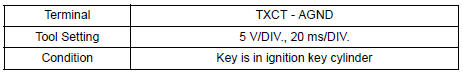
- Inspect using an oscilloscope.
- Waveform 1 (Reference):
- Waveform 2 (Reference):
 Problem symptoms table
ENGINE IMMOBILISER SYSTEM
...
 Diagnosis system
1. CHECK DLC3
The vehicle's ECU uses ISO 15765-4 for
communication protocol. The terminal arrangement
of the DLC3 complies with SAE J1962 and matches
the ISO 15765-4 format.
...
Other materials:
ABS Control System Malfunction
DTC 43 ABS Control System Malfunction
DESCRIPTION
This DTC is output when the VSC system detects a malfunction in the ABS
control system.
INSPECTION PROCEDURE
NOTICE:
When replacing the brake actuator assembly, perform zero point calibration
(See page BC-70).
1 CHECK ABS CONTROL SYSTEM
( ...
System description
1. MULTIPLEX COMMUNICATION SYSTEM (BEAN)
The BEAN communication line is used to control the
combination meter, the A/C amplifier, the airbag
sensor assembly, the multiplex network body ECU,
the power slide door ECU LH, the power slide door
ECU RH, the power back door ECU, the seat
posi ...
ECM / PCM Internal Engine Off Timer Performance
DTC SUMMARY
DESCRIPTION
To ensure the accuracy of the EVAP (Evaporative Emission) monitor values, the
soak timer, which is built
into the ECM, measures 5 hours (+/- 15 minutes) from when the ignition switch is
turned off, before the
monitor is run. This allows the fuel to cool down, whic ...
