Toyota Sienna Service Manual: Test mode procedure
1. SPEED SENSOR SIGNAL CHECK (WHEN USING SST CHECK WIRE):
HINT:
- If the ignition switch is turned from the ON to the ACC or LOCK position during Test Mode, the DTCs of the signal check function will be erased.
(a) Turn the ignition switch off.
(b) Check that the steering wheel is in the straightahead position and move the shift lever to the P position (Automatic Transmission) or apply the parking brake (Manual Transmission).
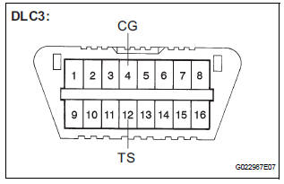
(c) Using SST, connect terminals TS and CG of the DLC3.
SST 09843-18040
(d) Turn the ignition switch to the ON position.
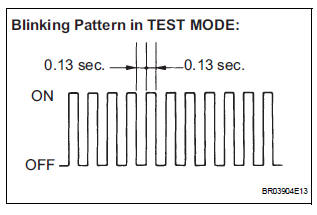
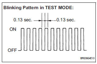
(e) Check that the ABS warning light is blinking in the Test Mode.
HINT:
If the ABS warning light does not blink, inspect the
TS and CG terminal circuit and the ABS warning
light circuit.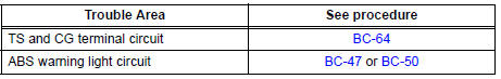
(f) Start the engine.
(g) Using SST, perform the speed sensor signal check in Test Mode.
SST 09843-18040
(h) Drive the vehicle straight forward.
(i) Accelerate the vehicle to a speed of 28 mph (45 km/ h) or higher for several seconds and check that the ABS warning light goes off.
HINT: The signal check may not be completed if the vehicle has its wheels spun.
(j) Stop the vehicle.
NOTICE:
- The speed sensor signal check may not be completed if the steering wheel is turned or the wheels are spun during the check.
- After the ABS warning light goes off and if
vehicle speed exceeds 50 mph (80 km/h), the
signal check code will be stored again.
Decelerate or stop the vehicle before the speed reaches 50 mph (80 km/h).
- If the signal check has not been completed, the ABS warning light blinks while driving and the ABS system does not operate.
HINT: When the signal check has been completed, the ABS warning light goes off while driving and blinks in the Test Mode pattern while stationary.
2. READ DTC
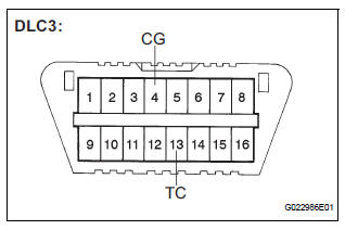
(a) Using SST, connect terminals TC and CG of the DLC3.
SST 09843-18040
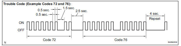
(b) Read the number of blinks of the ABS warning light.
HINT:
- See the list of DTC.
- If every sensor is normal, the normal system code is output. (A cycle of 0.25 second ON and 0.25 second OFF is repeated.)
- If more than 1 malfunction is detected at the same time, the lowest numbered code will be displayed first.
(c) After performing the check, disconnect the SST from terminals TS and CG, TC and CG of the DLC3 and turn the ignition switch off.
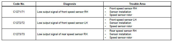
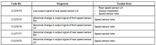
3. DTC OF TEST MODE (SIGNAL CHECK) FUNCTION
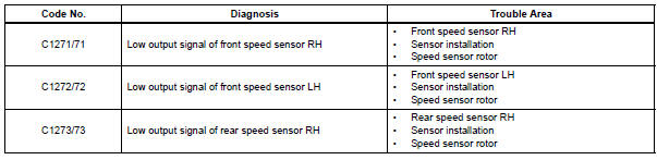
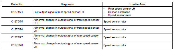
HINT: The codes in this table are output only in Test Mode (signal check).
4. SPEED SENSOR SIGNAL CHECK (WHEN USING INTELLIGENT TESTER):
HINT:
- If the ignition switch is turned from the ON to the ACC or LOCK position during Test Mode, DTCs of the signal check function will be erased.
- During Test Mode, the ECU records all DTCs of the signal check function. By performing the signal check, the codes are erased if normality is confirmed. The remaining codes are the codes where an abnormality was found.
(a) Turn the ignition switch off.
(b) Check that the steering wheel is in the straightahead position.
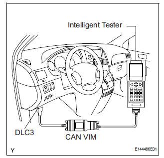
(c) Connect the intelligent tester to the DLC3.
(d) Turn the ignition switch to the ON position.
(e) Set the intelligent tester to Test Mode (select "SIGNAL CHECK").
HINT: Refer to the intelligent tester operator's manual for further details.
(f) Check that the ABS warning light is blinking in the Test Mode.
HINT:
If the ABS warning light does not blink, inspect the
TS and CG terminal circuit and the ABS warning
light circuit.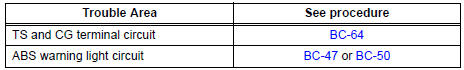
(g) Start the engine.
(h) Using the intelligent tester, perform the speed sensor signal check in Test Mode.
(i) Drive the vehicle straight forward.
(j) Accelerate the vehicle to a speed of 28 mph (45 km/ h) or higher for several seconds and check that the ABS warning light goes off.
HINT: The signal check may not be completed if the vehicle has its wheels spun.
(k) Stop the vehicle.
NOTICE:
- The speed sensor signal check may not be completed if the steering wheel is turned or the wheels are spun during the check.
- After the ABS warning light goes off and if
vehicle speed exceeds 50 mph (80 km/h), a
signal check code will be stored again.
Decelerate or stop the vehicle before the speed reaches 50 mph (80 km/h).
- If the signal check has not been completed, the ABS warning light blinks while driving and the ABS system does not operate.
HINT: When the signal check has been completed, the ABS warning light goes off while driving and blinks in the Test Mode pattern while stationary.
5. READ DTC
(a) Read the DTC(s) by following the tester screen.
HINT:
- Refer to the intelligent tester operator's manual for further details.
- See the list of DTC.
6. DTC OF TEST MODE (SIGNAL CHECK) FUNCTION
HINT: The codes in this table are output only in Test Mode (signal check).
 How to proceed with troubleshooting
The intelligent tester can be used at steps 3, 7, 10, and 13.
1 VEHICLE BROUGHT TO WORKSHOP
2 CUSTOMER PROBLEM ANALYSIS
(a) Interview the customer to confirm the trouble.
3 DTC CHECK/CLEAR AND ...
 Problem symptoms table
If there are no DTCs output but the problem still occurs,
check the circuits for each problem symptom in the order
given in the table below and proceed to the relevant
troubleshooting page.
NOTICE ...
Other materials:
On-vehicle inspection
1. INSPECT SIDE AIRBAG SENSOR (VEHICLE NOT
INVOLVED IN COLLISION)
Perform a diagnostic system check.
2. INSPECT SIDE AIRBAG SENSOR (VEHICLE
INVOLVED IN COLLISION AND AIRBAG HAS NOT
DEPLOYED)
Perform a diagnostic system check.
When the center pillar of the vehicle or ...
Right Rear Wheel Speed Sensor Signal
DESCRIPTION
Refer to DTCs C0200/31, C0205/32, C1235/35 and C1236/36 (See page BC-92).
HINT:
DTC C0210/33 and C1238/38 are for the right rear speed sensor.
DTC C0215/34 and C1239/39 are for the left rear speed sensor.
WIRING DIAGRAM
INSPECTION PROCEDURE
1 READ VALUE ON INTELL ...
Reassembly
1. INSTALL SEAT POSITION AIRBAG SENSOR (for Driver Seat)
2. INSTALL FRONT SEAT CUSHION SHIELD LOWER LH
Install the front seat cushion shield lower LH with
the screw.
3. INSTALL FRONT SEAT CUSHION SHIELD LOWER
RH
HINT:
Use the same procedures for the RH side and LH side.
4. INSTAL ...
