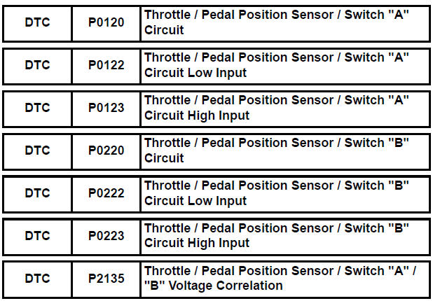
Toyota Sienna Service Manual: Throttle / Pedal Position Sensor / Switch "A"
HINT:
These DTCs relate to the Throttle Position (TP) sensor.
DESCRIPTION
HINT:
This ETC (Electrical Throttle Control System) does not use a throttle cable.
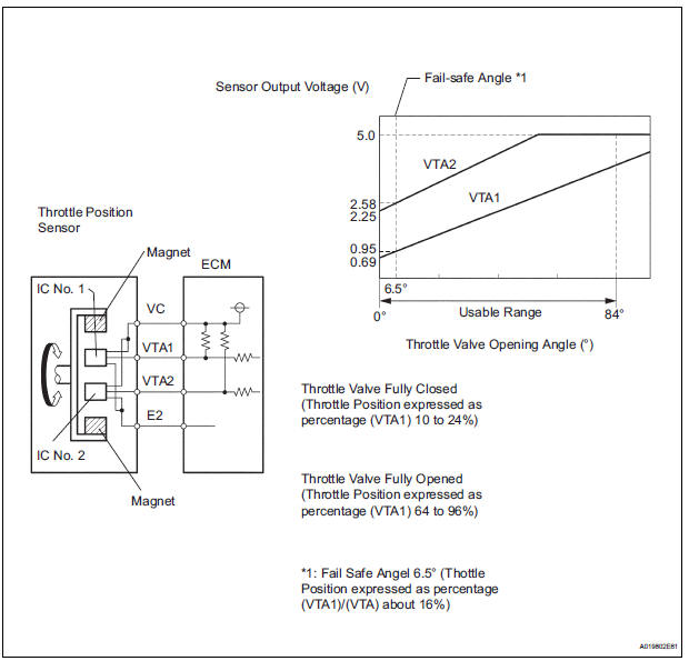
The Throttle Position (TP) sensor is mounted on the throttle body, and detects the opening angle of the throttle valve. This sensor is a non-contact type, and uses Hall-effect elements, in order to yield accurate signals, even in extreme driving conditions, such as at high speeds as well as very low speeds.
The TP sensor has two sensor circuits which each transmits a signal, VTA1 and VTA2. VTA1 is used to detect the throttle valve angle and VTA2 is used to detect malfunctions in VTA1. The sensor signal voltages vary between 0 V and 5 V in proportion to the throttle valve opening angle, and are transmitted to the VTA terminals of the ECM.
As the valve closes, the sensor output voltage decreases and as the valve opens, the sensor output voltage increases. The ECM calculates the throttle valve opening angle according to these signals and controls the throttle actuator in response to driver inputs. These signals are also used in calculations such as air-fuel ratio correction, power increase correction and fuel-cut control.
HINT:
- When any of these DTCs are set, check the throttle valve opening angle by selecting the following menu items on the intelligent tester: DIAGNOSIS / ENHANCED OBD II / DATA LIST / ETCS / THROTTLE POS AND THROTTLE POS #2.
- THROTTLE POS denotes the VTA1 signal (expressed in percentages), and THROTTLE POS #2 denotes the VTA2 signal (expressed in voltages).
Reference (Normal Condition) 
MONITOR DESCRIPTION
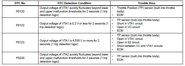
The ECM uses the Throttle Position (TP) sensor to monitor the throttle valve opening angle. There are several checks that the ECM performs to confirm the proper operation of the TP sensor.
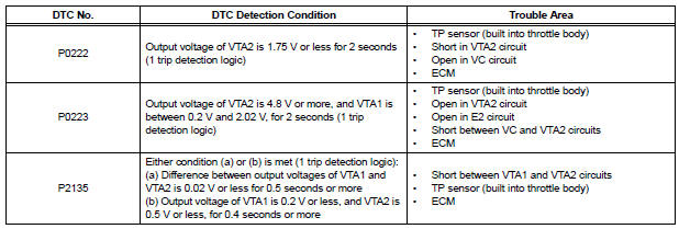
- A specific voltage difference is expected between the sensor terminals, VTA1 and VTA2, for each throttle valve opening angle. If the difference between VTA1 and VTA2 is incorrect, the ECM interprets this as a malfunction in the sensor, and sets a DTC.
- VTA1 and VTA2 each have a specific voltage range. If VTA1 or VTA2 is outside the normal operating range, the ECM interprets this as a malfunction in the sensor, and sets a DTC.
- VTA1 and VTA2 should never be close to the same voltage level. If VTA1 is within 0.02 V of VTA2, the ECM determines that there is a short circuit in the sensor, and sets a DTC.
If the malfunction is not repaired successfully, a DTC is set 2 seconds after the engine is next started.
MONITOR STRATEGY
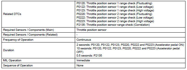
TYPICAL ENABLING CONDITIONS

TYPICAL MALFUNCTION THRESHOLDS
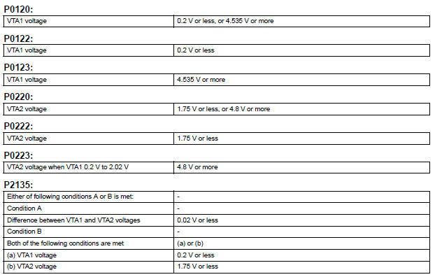
COMPONENT OPERATING RANGE

FAIL-SAFE
When any of these DTCs, as well as other DTCs relating to ETCS (Electronic Throttle Control System) malfunctions, are set, the ECM enters fail-safe mode. During fail-safe mode, the ECM cuts the current to the throttle actuator off, and the throttle valve is returned to a 6.5° throttle angle by the return spring. The ECM then adjusts the engine output by controlling the fuel injection (intermittent fuel-cut) and ignition timing, in accordance with the accelerator pedal opening angle, to allow the vehicle to continue at a minimal speed. If the accelerator pedal is depressed slowly, the vehicle can be driven slowly.
Fail-safe mode continues until a pass condition is detected, and the ignition switch is turned off.
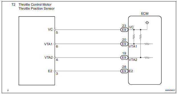
WIRING DIAGRAM
INSPECTION PROCEDURE
HINT:
- If other DTCs relating to different systems that have terminal E2 as the ground terminal are output simultaneously, terminal E2 may have an open circuit
- Read freeze frame data using the intelligent tester. The ECM records vehicle and driving condition information as freeze frame data the moment a DTC is stored. When troubleshooting, freeze frame data can be helpful in determining whether the vehicle was running or stopped, whether the engine was warmed up or not, whether the air-fuel ratio was lean or rich, as well as other data recorded at the time of a malfunction.
1 READ VALUE OF INTELLIGENT TESTER (THROTTLE POS AND THROTTLE POS #2)
(a) Connect the intelligent tester to the DLC3.
(b) Turn the ignition switch to the ON position and turn the intelligent tester on.
(c) Select the following menu items: DIAGNOSIS / ENHANCED OBD II / DATA LIST / ETCS / THROTTLE POS and THROTTLE POS #2.
(d) Check the values displayed on the tester.
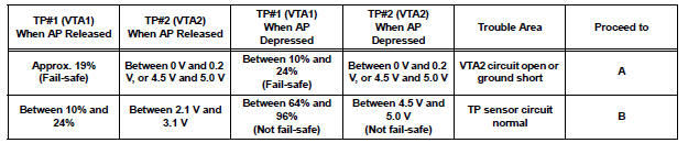
HINT:
- TP#1 denotes THROTTLE POS, and TP#2 denotes THROTTLE POS#2.
- AP denotes Accelerator Pedal.
- VTA1 is expressed as percentage, and VTA2 is expressed as voltage.


2 CHECK HARNESS AND CONNECTOR (THROTTLE POSITION SENSOR - ECM)
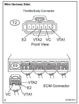
(a) Disconnect the T2 throttle body connector.
(b) Disconnect the E9 ECM connector.
(c) Measure the resistance according to the value(s) in the table below.
Standard resistance: 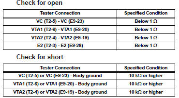
(d) Reconnect the throttle body connector.
(e) Reconnect the ECM connector.

3 INSPECT ECM (VC VOLTAGE)
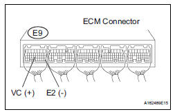
(a) Disconnect the T2 throttle body connector.
(b) Turn the ignition switch to the ON position.
(c) Measure the voltage according to the value(s) in the table below.
Standard voltage 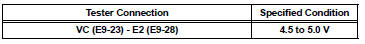
(d) Reconnect the throttle with motor body connector.


4 REPLACE THROTTLE BODY
(a) Replace the throttle body (See page ES-493).

5 CHECK WHETHER DTC OUTPUT RECURS (THROTTLE POSITION SENSOR DTCS)
(a) Connect the intelligent tester to the DLC3.
(b) Turn the ignition switch to the ON position and turn the tester on.
(c) Clear the DTCs (See page ES-39).
(d) Start the engine.
(e) Allow the engine to idle for 15 seconds or more.
(f) Select the following menu items: DIAGNOSIS / ENHANCED OBD II / DTC INFO / CURRENT CODES.
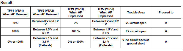
(g) Read the DTCs.
Result 


REPLACE ECM (See page ES-498)
 Engine Coolant Temperature / Intake Air Temperature Correlation
DESCRIPTION
The ECM calculates the difference between the readings of the coolant
temperature sensor and intake air
temperature sensor. If the difference is greater than 20°C (68°F), the ECM ...
 Throttle / Pedal Position Sensor / Switch "A" Circuit Range / Performance
Problem
Throttle / Pedal Position Sensor / Switch "A" Circuit Range / Performance
Problem
HINT:
This DTC relates to the Throttle Position (TP) sensor.
DESCRIPTION
Refer to DTC P0120 (See page ES-145).
MONITOR DESCRIPTION
The ECM uses the TP sensor to monitor the throttle valve ...
Other materials:
Removal
1. REMOVE INSTRUMENT CLUSTER CENTER NO. 1 FINISH PANEL
2. REMOVE INSTRUMENT CLUSTER CENTER NO. 2
FINISH PANEL
3. REMOVE SHIFT LEVER KNOB SUB-ASSEMBLY
4. REMOVE POSITION INDICATOR HOUSING ASSEMBLY
5. REMOVE INSTRUMENT CLUSTER CENTER LOWER FINISH PANEL SUB-ASSEMBLY
6. REMOVE POWER POINT SOCKET A ...
Installation
1. INSTALL TIRE PRESSURE WARNING VALVE AND TRANSMITTER
(a) Insert the tire pressure warning valve and
transmitter into the valve installation hole. Insert it
from the inside of the rim so that the printed surface
can be seen.
NOTICE:
Check that there is no visible deformation,
damage, ...
Warning light and indicator light bulb check
(a) Check the warning lights.
(1) Release parking brake pedal.
(2) When the ignition switch is turned to the ON
position, check that the ABS warning light,
BRAKE warning light, VSC warning light, TRAC
OFF indicator light (2WD) and SLIP indicator
light stay on for approx. 3 seconds.
HI ...
