Toyota Sienna Service Manual: Tire Pressure Warning Reset Switch Circuit
DESCRIPTION
The ECU enters the initialization mode and performs initialization automatically, when the tire pressure warning ECU receives the signal from the tire pressure warning reset switch. If the ECU receives the signal, the tire pressure warning light blinks 3 times (1 second on, 1 second off).
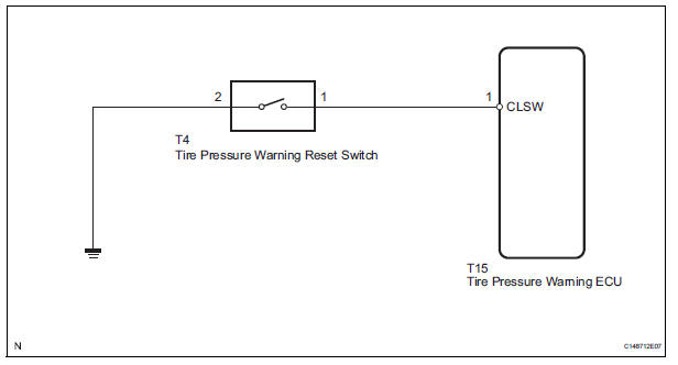
WIRING DIAGRAM
INSPECTION PROCEDURE
1 CHECK TIRE PRESSURE WARNING RESET SWITCH FUNCTION
(a) Perform the tire pressure warning reset switch test in TEST MODE PROCEDURE (See page TW-25).
OK: Reset switch ON: Tire pressure warning light comes on.
Reset switch OFF: Tire pressure warning light blinks.

END
2 INSPECT TIRE PRESSURE WARNING RESET SWITCH
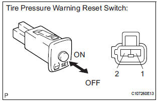
(a) Disconnect the tire pressure warning reset switch connector.
(b) Measure the resistance between terminals 1 and 2 of the tire pressure warning reset switch when the tire pressure warning switch is ON and OFF.
Standard resistance 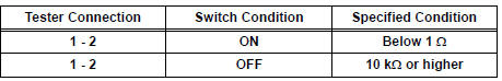
3 CHECK HARNESS AND CONNECTOR (TIRE PRESSURE WARNING RESET SW - TIRE PRESSURE WARNING ECU)
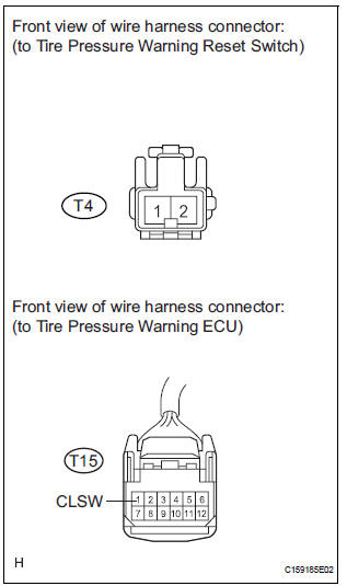
(a) Disconnect the tire pressure warning reset switch T4 connector and tire pressure warning ECU T15 connector.
(b) Measure the resistance according to the value(s) in the table below.
Standard resistance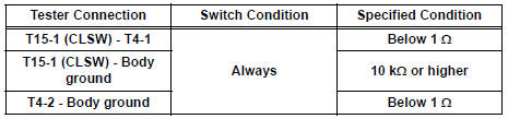

REPLACE TIRE PRESSURE WARNING ECU (See page TW-87)
 Vehicle Speed Signal Error (Test Mode DTC)
DTC C2191/91 Vehicle Speed Signal Error (Test Mode DTC)
DESCRIPTION
The tire pressure warning ECU receives a speed signal from the combination
meter. This DTC is stored
upon entering test mode, a ...
 Tire Pressure Warning Light Circuit
DESCRIPTION
If the ECU detects trouble, the tire pressure warning light blinks (comes on
after blinking for 1 minute) and
tire pressure monitor is cancelled at the same time. At this time, the ECU ...
Other materials:
Rear Clearance Sonar Sensor RH Circuit
DESCRIPTION
An ultrasonic sensor consists of a sensor portion that transmits and receives
ultrasonic waves and a preamplifier
that amplifies them. The ultrasonic sensor outputs the ultrasonic waves and
sends the received
signals to the clearance warning ECU.
WIRING DIAGRAM
INSPECTION PR ...
Command list
Some recognizable voice commands and their actions are shown
below as examples.
Basic
Command
Action
“Help”
Prompts voice guidance to offer examples of commands
or operation methods
“Go Back”
Returns to the previous screen
Phone
...
Vehicle Speed Sensor Malfunction
DTC P0500 Vehicle Speed Sensor Malfunction
DTC P0503 Vehicle Speed Sensor Circuit Malfunction
DESCRIPTION
The cruise control system uses the same vehicle speed signal that is sent to
the ECM for the SFI system.
If DTC P0500 is detected, perform the diagnosis using the inspection procedure
...
