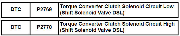
Toyota Sienna Service Manual: Torque Converter Clutch Solenoid Circuit
DESCRIPTION
The shift solenoid valve DSL is turned "ON" and "OFF" by signals from the ECM
in order to control the
hydraulic pressure operation, the lock-up relay valve, which then controls
operation of the lock-up clutch.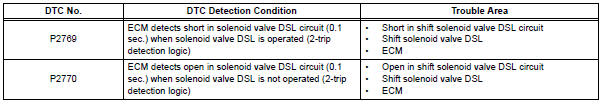
MONITOR DESCRIPTION
Torque converter lock-up is controlled by the ECM based on engine rpm, engine load, engine temperature, vehicle speed, transmission temperature, and shift range selection. The ECM determines the lock-up status of the torque converter by comparing the engine rpm (NE) to the input turbine rpm (NT).
The ECM calculates the actual transmission gear by comparing input turbine rpm (NT) to counter gear rpm (NC). When conditions are appropriate, the ECM requests "lock-up" by applying control voltage to the shift solenoid DSL. When the DSL is opened, it applies pressure to the lock-up relay valve and locks the torque converter clutch. If the ECM detects an open or short in the DSL solenoid circuit, the ECM interprets this as a fault in the DSL solenoid or circuit. The ECM will turn on the MIL and store the DTC.
MONITOR STRATEGY
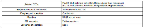
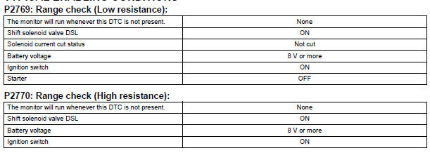
TYPICAL ENABLING CONDITIONS

TYPICAL MALFUNCTION THRESHOLDS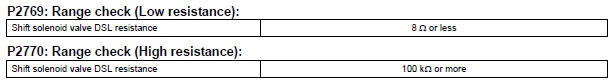
COMPONENT OPERATING RANGE
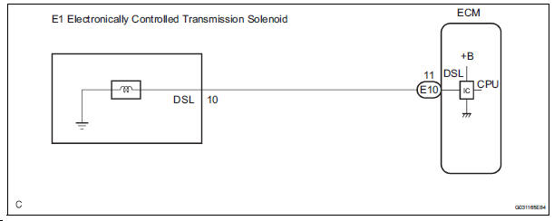
WIRING DIAGRAM
INSPECTION PROCEDURE
1 INSPECT TRANSMISSION WIRE (DSL)
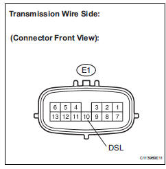
(a) Disconnect the transmission wire connector from the transaxle.
(b) Measure the resistance according to the value(s) in the table below.
Standard resistance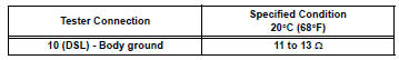

2 CHECK HARNESS AND CONNECTOR (TRANSMISSION WIRE - ECM)
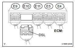
(a) Connect the transmission wire connector.
(b) Disconnect the ECM connector.
(c) Measure the resistance according to the value(s) in the table below.
Standard resistance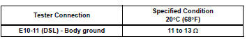

REPLACE ECM
3 INSPECT SHIFT SOLENOID VALVE DSL
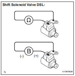
(a) Remove the shift solenoid valve DSL.
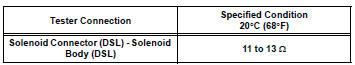
(b) Measure the resistance according to the value(s) in the table below.
Standard resistance
(c) Connect the positive (+) lead to the terminal of the solenoid connector, and the negative (-) lead to the solenoid body.
OK: The solenoid valve makes an operating sound.

REPAIR OR REPLACE TRANSMISSION WIRE
 Pressure Control Solenoid "D" Electrical (Shift
Solenoid Valve SLT)
Pressure Control Solenoid "D" Electrical (Shift
Solenoid Valve SLT)
DESCRIPTION
The linear solenoid valve (SLT) controls the transmission line pressure for
smooth transmission operation
based on signals from the throttle position sensor and the vehicle speed senso ...
Other materials:
Diagnosis system
1. CHECK DLC3
The ECU uses ISO 15765-4 for communication.
The terminal arrangement of the DLC3 complies
with SAE J1962 and matches the ISO 15765-4
format.
NOTICE:
*: Before measuring the resistance, leave the
vehicle as is for at least 1 minute and do not
operate the ig ...
Ignition Switch Circuit
DESCRIPTION
The Multiplex network body ECU receives the ACC and IG signals from the
ignition switch.
WIRING DIAGRAM
INSPECTION PROCEDURE
1 READ VALUE OF INTELLIGENT TESTER
Connect the intelligent tester to DLC3.
Turn the ignition switch ON and push the intelligent
tester main ...
Installation
1. INSTALL CENTER REAR SEAT LAP TYPE BELT
ASSEMBLY (for 8-Passenger)
HINT:
Refer to the instructions for reassembly of the rear No. 1
seat assembly (for center seat).
Install the center rear seat lap type belt assembly
with the bolt.
Torque: 42 N*m (430 kgf*cm, 31 ft.*lbf)
2. IN ...
