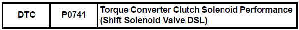
Toyota Sienna Service Manual: Torque Converter Clutch Solenoid Performance (Shift Solenoid Valve DSL)
SYSTEM DESCRIPTION
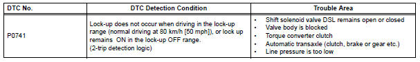
The ECM uses the signals from the throttle position sensor, air-flow meter, turbine (input) speed sensor, intermediate (counter) shaft speed sensor and crankshaft position sensor to monitor the engagement condition of the lock-up clutch.
Then the ECM compares the engagement condition of the lock-up clutch with the lock-up schedule in the ECM memory to detect a mechanical problems of the shift solenoid valve DSL, valve body and torque converter clutch.
MONITOR DESCRIPTION
Torque converter lock-up is controlled by the ECM based on the speed sensor (NT), speed sensor (NC), engine rpm, engine load, engine temperature, vehicle speed, transmission temperature, and gear selection. The ECM determines the lock-up status of the torque converter by comparing the engine rpm (NE) to the input turbine rpm (NT). The ECM calculates the actual transmission gear by comparing input turbine rpm (NT) to counter gear rpm (NC). When conditions are appropriate, the ECM requests "lock-up" by applying control voltage to the shift solenoid DSL. When the DSL is turned on, it applies pressure to the lock-up relay valve and locks the torque converter clutch.
If the ECM detects no lock-up after lock-up has been requested or if it detects lock-up when it is not requested, the ECM interprets this as a fault in the shift solenoid valve DSL or lock-up system performance. The ECM will turn on the MIL and store the DTC.
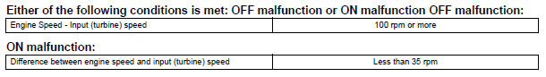
HINT: Example: When any of the following is met, the system judges it as a malfunction.
- There is a difference in rotation between the input side (engine speed)
and output side (input turbine
speed) of the torque converter when the ECM commands lock-up.
(Engine speed is at least 100 rpm greater than input turbine speed.)
- There is no difference in rotation between the input side (engine speed)
and output side (input turbine
speed) of the torque converter when the ECM commands lock-up off.
(The difference between engine speed and input turbine speed is less than 35 rpm.)
MONITOR STRATEGY
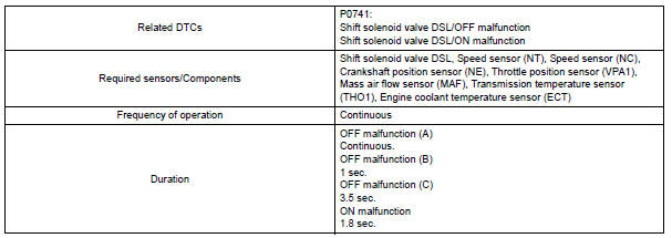

TYPICAL ENABLING CONDITIONS
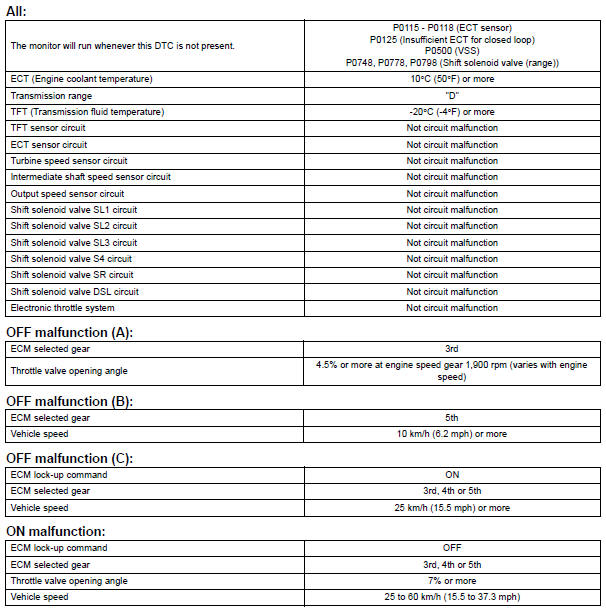
TYPICAL MALFUNCTION THRESHOLDS
INSPECTION PROCEDURE
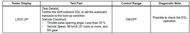
HINT: Using the intelligent tester to perform ACTIVE TEST allows relays, VSVs, actuators and other items to be operated without removing any parts. This non-intrusive functional inspection can be very useful because intermittent operation may be discovered before parts or wiring is disturbed. Performing ACTIVE TEST early in troubleshooting is one way to save diagnostic time. DATA LIST information can be displayed while performing ACTIVE TEST.
1. PERFORM ACTIVE TEST
(a) Warm up the engine.
(b) Turn the ignition switch off.
(c) Connect the intelligent tester together with the CAN VIM (controller area network vehicle interface module) to the DLC3.
(d) Turn the ignition switch to the ON position.
(e) Turn on the tester.
(f) Select the item "DIAGNOSIS / ENHANCED OBD II / ACTIVE TEST".
(g) According to the display on the tester, perform the "ACTIVE TEST".
HINT:
- This test can be conducted when the vehicle speed is 60 km/h (37 mph) or more.
- This test can be conducted in the 5th gear.
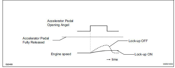
(h) Lightly depress the accelerator pedal and check that the engine speed does not change abruptly.
HINT:
- When changing the accelerator pedal opening angle while driving, if the engine speed does not change, lock-up is on.
- Slowly release, but not fully, the accelerator pedal in order to decelerate. (Fully releasing the pedal will close the throttle valve and lock-up may be turned off.)
1 CHECK OTHER DTCS OUTPUT (IN ADDITION TO DTC P0741)
(a) Connect the intelligent tester together with the CAN VIM (controller area network vehicle interface module) to the DLC3.
(b) Turn the ignition switch to the ON position and turn the OBD II scan tool or the intelligent tester main switch ON.
(c) When you use intelligent tester: Select the item "DIAGNOSIS / ENHANCED OBD II / DTC INFO / CURRENT CODES".
(d) Read the DTCs using the OBD II scan tool or the intelligent tester.
Result 
HINT: If any other codes besides "P0741" are output, perform the troubleshooting for those DTCs first.


2 INSPECT TRANSMISSION WIRE (DSL)
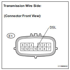
(a) Disconnect the transmission wire connector from the transaxle.
(b) Measure the resistance according to the value(s) in the table below.
Standard resistance
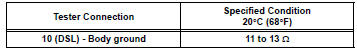


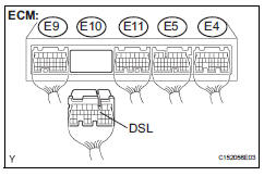
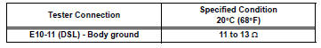
3 CHECK HARNESS AND CONNECTOR (TRANSMISSION WIRE - ECM)
(a) Connect the transmission wire connector.
(b) Disconnect the ECM connector.
(c) Measure the resistance according to the value(s) in the table below.
Standard resistance

4 INSPECT SHIFT SOLENOID VALVE DSL
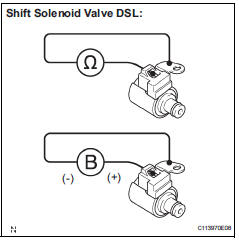
(a) Remove the shift solenoid valve DSL.
(b) Measure the resistance according to the value(s) in the table below.
Standard resistance
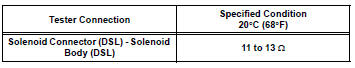
(c) Connect the positive (+) lead to the terminal of the solenoid connector, and the negative (-) lead to the solenoid body.
OK: The solenoid valve makes an operating sound.


5 CHECK TRANSMISSION WIRE
OK: The connectors and pins are securely installed.
There is no open or short on the wire harness.

6 INSPECT TRANSMISSION VALVE BODY ASSEMBLY
OK: There are no foreign objects on each valve and they operate smoothly.

7 INSPECT TORQUE CONVERTER CLUTCH ASSEMBLY
OK: The torque converter clutch operates normally.

REPAIR AUTOMATIC TRANSAXLE ASSEMBLY
 Brake Switch "B" Circuit High
DESCRIPTION
The purpose of this circuit is to prevent the engine from stalling while
driving in lock-up condition when
brakes are suddenly applied.
When the brake pedal is depressed, this s ...
 Pressure Control Solenoid "A" Performance (Shift Solenoid
Valve SL1)
Pressure Control Solenoid "A" Performance (Shift Solenoid
Valve SL1)
SYSTEM DESCRIPTION
The ECM uses signals from the vehicle speed sensor to
detect the actual gear position (1st, 2nd, 3rd, 4th
or 5th gear).
Then the ECM compares the actual gear with the shi ...
Other materials:
Throttle Actuator Control Motor Current Range / Performance
DESCRIPTION
The ETCS (Electronic Throttle Control System) has a dedicated power supply
circuit. The voltage (+BM)
is monitored and when it is low (less than 4 V), the ECM determines that there
is a malfunction in the
ETCS and cuts off the current to the throttle actuator.
When the volt ...
Opening/closing the sliding door
Sliding door handle
Open/close
Vehicles with power sliding
doors: The sliding door will be
automatically and completely
opened and closed by the following.
Pulling the outside handle.
Sliding the inside handle forward
to close or backward to
open.
Power sliding door switches (v ...
How to proceed with
troubleshooting
HINT:
Troubleshoot in accordance with the procedures on the
following pages.
1 VEHICLE BROUGHT TO WORKSHOP
2 CUSTOMER PROBLEM ANALYSIS CHECK AND SYMPTOM CHECK
3 PROBLEM SYMPTOMS TABLE
When problem is not listed on problem symptoms table,
proceed to A.
When problem is listed on pro ...
