Toyota Sienna Service Manual: Transmission Range Sensor Circuit Malfunction (PRNDL Input)
 DESCRIPTION
The park/neutral position switch detects the shift lever position and sends signals to the ECM.

MONITOR DESCRIPTION
These DTCs indicate a problem with the park/neutral position switch and the wire harness in the park/ neutral position switch circuit.
The park/neutral position switch detects the shift lever position and sends a signal to the ECM.
For security, the park/neutral position switch detects the shift lever position so that engine can be started only when the shift lever is in the P or N position The park/neutral position switch sends a signal to the ECM according to the shift position (P, R, N or D).
The ECM determines that there is a problem with the switch or related parts if in receives more than 1 position signal simultaneously. The ECM will turn on the MIL and store the DTC.
MONITOR STRATEGY
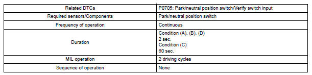
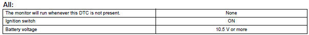
TYPICAL ENABLING CONDITIONS
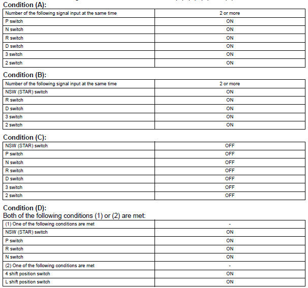
TYPICAL MALFUNCTION THRESHOLDS
1. One of the following conditions are met: Condition (A), (B), (C) and (D)
COMPONENT OPERATING RANGE
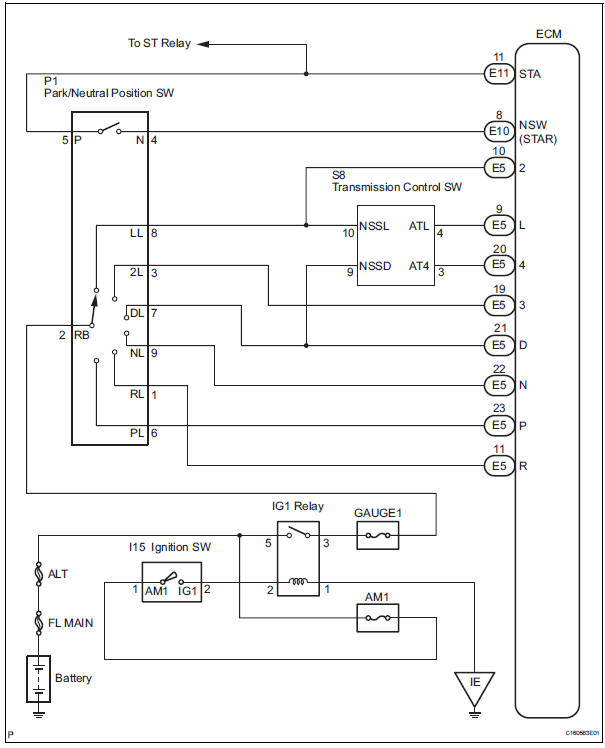
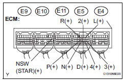
WIRING DIAGRAM
1 INSPECT PARK/NEUTRAL POSITION SWITCH ASSEMBLY
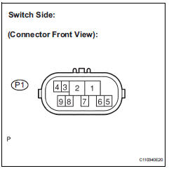
(a) Disconnect the park/neutral position switch connector.
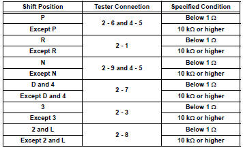
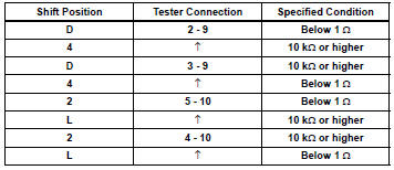
(b) Measure resistance according to the value(s) in the table below when the shift lever is moved to each position.
Standard resistance

2 INSPECT SHIFT LOCK CONTROL UNIT ASSEMBLY
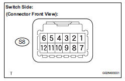
(a) Connect the park/neutral position switch connector.
(b) Disconnect the transmission control switch connector of shift lock control unit assembly.
(c) Measure resistance according to the value(s) in the table below when the shift lever is moved to each position.
Standard resistance

3 CHECK HARNESS AND CONNECTOR (PARK/NEUTRAL POSITION SWITCH - ECM)
(a) Connect the transmission control switch connector of shift lock control unit assembly.
(b) Turn the ignition switch to the ON position, and measure the voltage according to the value(s) in the table below when the shift lever is moved to each position.
Standard voltage
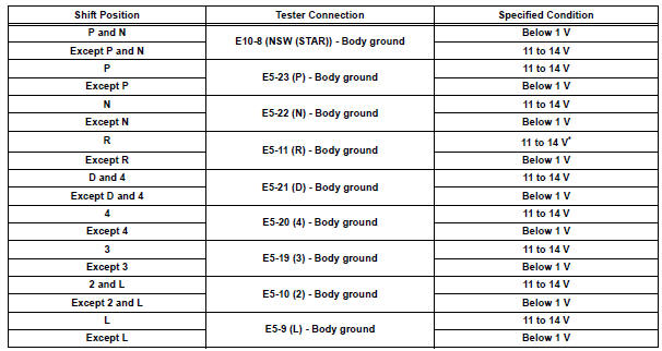
HINT: *: The voltage will drop slightly due to lighting up of the back up light.

REPLACE ECM
 Diagnostic trouble code chart
If a DTC is displayed during the DTC check, check the parts
listed in the table below and proceed to the page given.
HINT:
*1: Comes on MIL (Malfunction Indicator Lamp) light up
*2: "DT ...
 Transmission Fluid Temperature Sensor "A"
DESCRIPTION
The ATF (Automatic Transmission Fluid) temperature sensor converts the fluid
temperature into a
resistance value which is input into the ECM.
The ECM applies a voltage to the te ...
Other materials:
Diagnosis system
1. CHECK DLC3
The vehicle's ECU uses ISO 15765-4 for
communication protocol. The terminal arrangement
of the DLC3 complies with SAE J1962 and matches
the ISO 15765-4 format.
NOTICE:
*: Before measuring the resistance, leave the
vehicle as is for at least 1 minute and do not
...
Brake Warning Light Remains ON
DESCRIPTION
If the ECU detects a trouble, it turns on the brake warning light at the same
time of prohibiting ABS
control.
At this time, the ECU records a DTC in memory.
Connect terminals TC and CG of the DLC3 to make the brake warning light blink
and output the DTC.
WIRING DIAGRAM
...
Map Disc Read Error
DTC 58-42 Map Disc Read Error
DTC 80-42 Map Disc Read Error
DESCRIPTION
DTC No.
DTC Detection Condition
Trouble Area
58-42
Player error
Scratches or dirt on the disc
Access to an invalid address due to software error
...
