Toyota Sienna Service Manual: TS and CG Terminal Circuit
DESCRIPTION
The Test Mode (signal check) circuit detects trouble in the sensor or switch signal, which cannot be detected by the DTC check.
Connecting terminals TS and CG of the DLC3 starts the check.
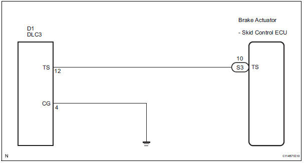
WIRING DIAGRAM
INSPECTION PROCEDURE
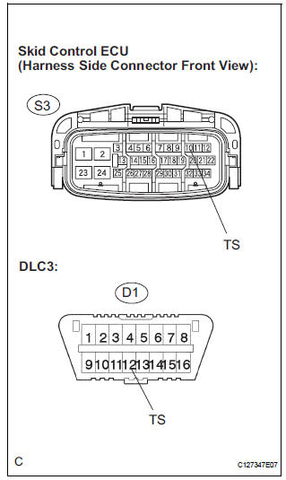
1 CHECK HARNESS AND CONNECTOR (BETWEEN SKID CONTROL ECU AND TS of DLC3)
(a) Turn the ignition switch off.
(b) Disconnect the skid control ECU connector.
(c) Measure the resistance according to the value(s) in the table below.
Standard resistance 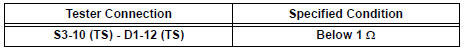

2 CHECK HARNESS AND CONNECTOR (BETWEEN CG of DLC3 AND BODY GROUND)
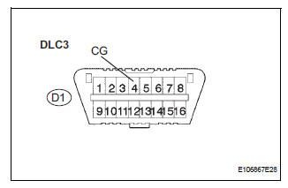
(a) Measure the resistance according to the value(s) in the table below.
Standard resistance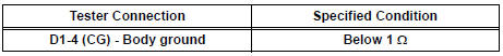

3 CHECK HARNESS AND CONNECTOR (BETWEEN TS of DLC3 AND BODY GROUND)
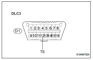
(a) Measure the resistance according to the value(s) in the table below.
Standard resistance 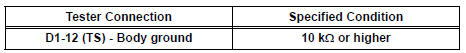

REPLACE BRAKE ACTUATOR ASSEMBLY
 TC and CG Terminal Circuit
DESCRIPTION
DTC output mode is set by connecting terminals TC and CG of the DLC3.
The DTCs are displayed by the blinking pattern of the ABS warning light.
WIRING DIAGRAM
HINT:
When warning ...
 Vehicle stability control system
Parts location
...
Other materials:
Installation
1. INSTALL INSTRUMENT PANEL SAFETY PAD SUBASSEMBLY
Using a torque wrench, install the bolt <B>.
Torque: 20 N*m (204 kgf*cm, 14 ft.*lbf)
2. INSTALL SHIFT LEVER ASSEMBLY
Using a torque wrench, install the 4 bolts.
Torque: 21 N*m (214 kgf*cm, 12.6 ft.*lbf)
3. ...
Removal
1. REMOVE REAR WHEEL
2. REMOVE TAIL EXHAUST PIPE ASSEMBLY (See page
EX-8)
3. SEPARATE REAR SPEED SENSOR
(a) Remove the bolt and the speed sensor from the
axle carrier.
NOTICE:
Be careful not to damage the speed sensor
Prevent foreign matter from adhering to the
speed sensor.
4. REMO ...
Front No. 2 speaker
COMPONENTS
ON-VEHICLE INSPECTION
1. INSPECT FRONT NO.2 SPEAKER
HINT:
Remove interior parts so that the front No.2 speaker can
be seen.
Check the speaker installation.
OK:
The speaker is securely installed.
If the result is not as specified, reinstall the front
No.2 speak ...
