Toyota Sienna Service Manual: Vehicle Speed Signal Circuit between Radio Receiver and Combination Meter
DESCRIPTION This circuit is necessary for the ASL (Auto Sound Leveliser) built into the radio receiver.
Speed signals are received from the combination meter and used for the ASL.
The ASL function automatically adjusts the sound data in order to enable hearing the clear audio sound even when vehicle noise increases (as vehicle noise increases, the volume is turned up etc.).
HINT:
- A voltage of 12 V or 5 V is output from each ECU and then input to the combination meter. The signal is changed to a pulse signal at the transistor in the combination meter. Each ECU controls the respective system based on the pulse signal.
- If a short occurs in an ECU, all systems in the diagram below will not operate normally.
WIRING DIAGRAM

INSPECTION PROCEDURE
1 CHECK OPERATION OF SPEEDOMETER
- Drive the vehicle and check if the function of the speedometer on the combination meter is normal.
OK: Actual vehicle speed and the speed indicated on the speedometer are the same.
HINT: the vehicle speed sensor is functioning normally when the indication on the speedometer is normal.
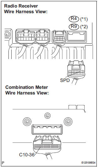
2 INSPECT RADIO RECEIVER
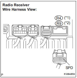
- Disconnect the radio receiver connector.
- Measure the voltage.
- Jack up either one of the drive wheels.
- Move the shift lever to the neutral position.
- Turn the ignition switch to the ON position.
*1: 6 Speaker without Rear Seat Entertainment System.
*2: 6 Speaker with Rear Seat Entertainment System.
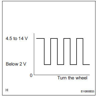
- Measure the voltage between terminal SPD of the radio receiver and body ground when the drive wheels are turned slowly.
OK: Voltage pulses as shown in the illustration.
3 CHECK HARNESS AND CONNECTOR (COMBINATION METER - RADIO RECEIVER)
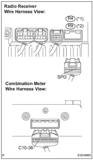
- Disconnect the radio receiver connector and combination meter connector.
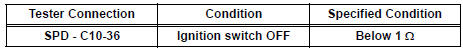
- Measure the resistance according to the value(s) in the table below.
Standard resistance
*1: 6 Speaker without Rear Seat Entertainment System.
*2: 6 Speaker with Rear Seat Entertainment System.
4 CHECK HARNESS AND CONNECTOR
- Disconnect the radio receiver connector and combination meter connector.
- Measure the resistance according to the value(s) in the table below.
Standard resistance
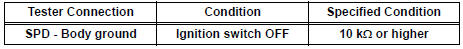
HINT: If the resistance between terminal SPD and body ground is less than 10 kΩ, there may be a short in a wire harness, connector, or an ECU that is connected to the SPD signal wire.
*1: 6 Speaker without Rear Seat Entertainment System.
*2: 6 Speaker with Rear Seat Entertainment System.
REPLACE COMBINATION METER
 Poor Sound Quality in All Modes (Low Volume)
INSPECTION PROCEDURE
1 CHECK AUDIO SETTINGS
Set "BASS", "MID", and "TREB" to the initial values and
check that sound is normal.
OK:
Malfunction disappears.
2 ...
 Steering Pad Switch Circuit
DESCRIPTION
This circuit sends an operation signal from the steering pad switch to the
radio receiver.
If there is an open in the circuit, the audio system cannot be operated using
the steerin ...
Other materials:
Perform zero point calibration of yaw rate and deceleration sensor (when
using sst check wire)
NOTICE:
While obtaining the zero point, do not vibrate the
vehicle by tilting, moving or shaking it and keep it
in a stationary condition. (Do not turn the ignition
switch to the ON position.)
Be sure to do this on a level surface (with an
inclination of less than 1 %).
(a) Proc ...
Problem symptoms table
HINT:
Use the table below to help determine the cause of the
problem symptom. The potential causes of the symptoms
are listed in order of probability in the "Suspected Area"
column of the table. Check each symptom by checking the
suspected areas in the order they are listed. Re ...
Receiver Error
DTC C2176/76 Receiver Error
DESCRIPTION
The signals are transmitted to the tire pressure warning antenna and receiver
on the body as radio waves
and then sent to the tire pressure warning ECU.
WIRING DIAGRAM
INSPECTION PROCEDURE
NOTICE:
When replacing the tire pressure warning EC ...
