Toyota Sienna Service Manual: Wiper switch
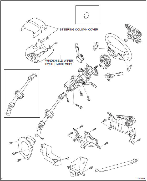
COMPONENTS
REMOVAL
1. REMOVE STEERING COLUMN COVER
2. REMOVE WINDSHIELD WIPER SWITCH ASSEMBLY
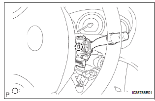
- Disconnect the connector.
- Using a screwdriver, disengage the claw and pull out the windshield wiper switch assembly.
NOTICE: The claw will be broken if pressed hard.
HINT: Tape up the screwdriver tip before use.
INSPECTION
1. INSPECT WINDSHIELD WIPER SWITCH ASSEMBLY
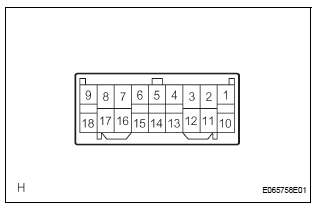
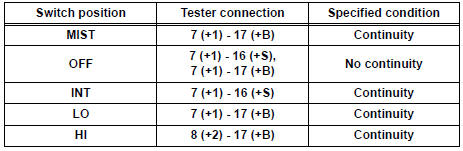
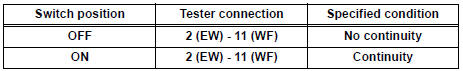
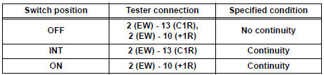
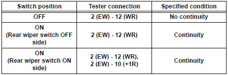
- Continuity Check
- Check the continuity between each of the terminals of the connector.
Standard:
Front Wiper Switch
Front Washer Switch
Rear Wiper Switch
Rear Washer Switch
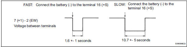
- Intermittent Operation Check
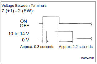
- Connect the voltmeter (+) terminal to the terminal 7 (+1) of the connector, the voltmeter (-) terminal to the terminal 2 (EW) of the connector.
- Connect the battery (+) to the terminal 17 (+B) of the connector, the battery (-) to the terminal 2 (EW) and the terminal 16 (+S) of the connector.
- Turn the wiper switch into the INT position.
- Connect the battery (+) to the terminal 16 (+S) of the connector for 5 seconds.
- Connect the battery (-) to the terminal 16 (+S) of the connector. Operate the intermittent wiper relay and check voltage between the terminal 7 (+1) and the terminal 2 (EW).
- Operation Check (Front Wiper)
- Turn the wiper switch into the OFF position.
- Connect the battery (+) to the terminal 17 (+B) of the connector, the battery (-) to the terminal 16 (+S) and 2 (EW) of the connector.
- Connect the voltmeter (+) terminal to the terminal 7 (+1) of the connector, the voltmeter (-) terminal to the terminal 2 (EW) of the connector. Turn the washer switch ON and OFF and check voltage between the terminal 7 (+1) and the terminal 2 (EW).
INSTALLATION
1. INSTALL WINDSHIELD WIPER SWITCH ASSEMBLY
2. REMOVE STEERING COLUMN COVER
 Rear wiper rubber
COMPONENTS
REMOVAL
1. REMOVE REAR WIPER BLADE ASSEMBLY
Remove the rear wiper arm head cap from the rear
wiper arm.
Raise the rear wiper blade to the position as shown
i ...
 Front washer motor
ON-VEHICLE INSPECTION
1. INSPECT FRONT WASHER MOTOR
Operation Check
Pour the water into the washer jar with the
windshield washer motor and pump installed to
the washer ...
Other materials:
Reassembly
1. INSTALL REAR SEAT STAY SUB-ASSEMBLY
Install the rear seat stay sub-assembly with the nut.
Torque: 5.5 N*m (56 kgf*cm, 49 in.*lbf)
2. INSTALL NO. 2 SEAT CUSHION SPRING ASSEMBLY
LH
3. INSTALL LOCUS CABLE LH
Install the locus cable LH with the nut.
Torque: 5.5 N*m (56 kg ...
Differential oil
Adjustment
1. INSPECT DIFFERENTIAL OIL
(a) Stop the vehicle on the level place.
(b) Remove the differential filler plug and gasket.
(c) Check that the oil surface is within 5 mm (0.20 in.)
from the lowest position of the inner surface of the
differential filler plug opening.
NOTICE:
...
Removal
HINT:
On the RH side, use the same procedures as on the LH side.
1. REMOVE SLIDE DOOR
Remove the rear door scuff plate (See page IR-7).
Remove the back door scuff plate (See page ED-
214).
Remove the quarter trim panel (See page IR-9).
Remove the upper rail cushion from the rail up ...
