Toyota Sienna Service Manual: Yaw Rate Sensor Communication Stop Mode
DESCRIPTION
|
Detection Item |
Symptom |
Trouble Area |
| Yaw Rate Sensor Communication Stop Mode |
|
|
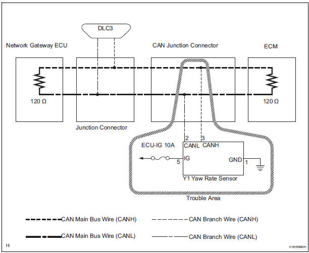
WIRING DIAGRAM
INSPECTION PROCEDURE
NOTICE:
- Turn the ignition switch off before measuring the resistances of CAN bus main wires and CAN bus branch wires.
- After the ignition switch is turned off, check that the key reminder warning system and light reminder warning system are not in operation.
- Before measuring the resistance, leave the vehicle as is for at least 1 minute and do not operate the ignition switch, any other switches, or the doors. If any doors need to be opened in order to check connectors, open the doors and leave them open.
HINT: Operating the ignition switch, any switches, or any doors triggers related ECU and sensor communication with the CAN. This communication will cause the resistance value to change.
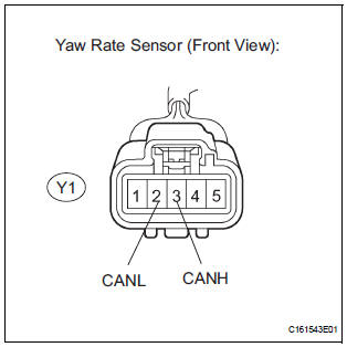
1 CHECK OPEN IN CAN BUS WIRE (YAW RATE SENSOR BRANCH WIRE)
- Turn the ignition switch off.
- Disconnect the yaw rate sensor connector.
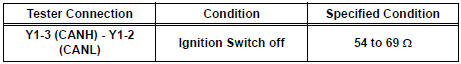
- Measure the resistance according to the value(s) in the table below.
Standard resistance
2 CHECK WIRE HARNESS (IG, GND)
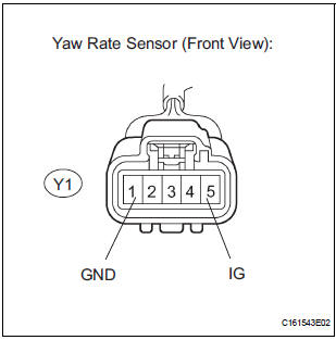
- Measure the resistance according to the value(s) in the table below.
Standard resistance
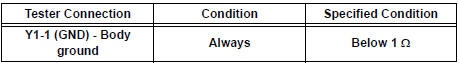
- Measure the voltage according to the value(s) in the table below.
Standard voltage
REPLACE YAW RATE SENSOR
 Steering Angle Sensor Communication Stop Mode
DESCRIPTION
Detection Item
Symptom
Trouble Area
Steering Angle Sensor
Communication Stop
Mode
"Steering angle sensor" is not displayed on ...
 ECM Communication Stop Mode
DESCRIPTION
Detection Item
Symptom
Trouble Area
ECM Communication Stop
Mode
"Engine" is not displayed on the "Communication
Bus Che ...
Other materials:
Installation
1. INSTALL PROPELLER W/CENTER BEARING SHAFT ASSEMBLY
(a) Align the matchmarks on the propeller shaft
assembly rear flange and differential companion
flange, and connect the shaft with the 4 bolts,
washers and nuts.
(b) Remove SST(s) from the extension housing.
(c) Insert the yoke int ...
Reassembly
1. INSTALL COOLER DRYER
(a) Using needle nose pliers, install the cooler dryer.
(b) Install a new O-ring on the cap.
(c) Sufficiently apply compressor oil to the fitting
surfaces of the O-ring and the cap.
Compressor oil:
ND-OIL 8 or equivalent
(d) Using a hexagon wrench 14 mm ( ...
Check component status
(a) Compare the test value with the minimum test limit
(MIN LIMIT) and maximum test limit (MAX LIMIT).
(b) If the test value is between the minimum test limit
and maximum test limit, the component is
functioning normally. If not, the component is
malfunctioning. The test value is usually sign ...
