Toyota Sienna Service Manual: A/F sensor and ho2s monitors
(a) Preconditions
The monitor will not run unless:
- 2 minutes or more have elapsed since the engine was started.
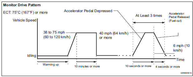
- The Engine Coolant Temperature (ECT) is 75°C (167°F) or more.
- Cumulative driving time at a vehicle speed of 30 mph (48 km/h) or more exceeds 6 minutes.
- Air-fuel ratio feedback control is performed.
- Fuel-cut control is performed for 8 seconds or more (for the Rear HO2 Sensor Monitor).
(b) Drive Pattern for front A/F sensor and HO2 sensor
(1) Connect an intelligent tester to the DLC3.
(2) Turn the ignition switch to the ON position.
(3) Turn the tester ON.
(4) Clear the DTCs.
(5) Start the engine, and warm it up until the ECT reaches 75°C (167°F) or higher.
(6) Drive the vehicle at 38 mph (60 km/h) or more for at least 10 minutes.
(7) Change the transmission to the 2nd gear.
(8) Accelerate the vehicle to 40 mph (64 km/h) or more by depressing the accelerator pedal for at least 10 seconds (Procedure "A").
(9) Soon after performing procedure "A" above, release the accelerator pedal for at least 4 seconds without depressing the brake pedal, in order to execute fuel-cut control (Procedure "B").
(10) Allow the vehicle to decelerate until the vehicle speed declines to less than 6 mph (10 km/h) (Procedure "C").
(11) Repeat procedures from "A" through "C" above at least 3 times in one driving cycle.
(c) Monitor Status
(1) Check the Readiness Monitor status displayed on the tester.
(2) If the status does not switch to COMPL (complete), make sure that the preconditions have been met and then perform the Drive Pattern again.
 Evap monitor (key-off type)
(a) Preconditions
The monitor will not run unless:
The fuel tank is less than 90% full.
The altitude is less than 8000 ft (2450 m).
The vehicle is stationary.
The engine coolant temperature ...
 Air-fuel ratio (a/f) and heated oxygen (ho2)
sensor heater monitors (front a/f and rear ho2 sensor
type)
Air-fuel ratio (a/f) and heated oxygen (ho2)
sensor heater monitors (front a/f and rear ho2 sensor
type)
(a) Preconditions
The monitor will not run unless:
The MIL is OFF.
(b) Drive Pattern
(1) Connect an intelligent tester to the DLC3.
(2) Turn the ignition switch to the ON position.
(3 ...
Other materials:
Diagnostic trouble code chart
COMMUNICATION DIAGNOSIS:
SW:
SW WITH NAME:
SW CONVERTING:
COMMAND SW:
FRONT MONITOR:
DVD PLAYER:
TELEPHONE:
NAVI:
IN-DASH CD CHANGER:
GPS:
CAMERA UNIT:
...
Ignition Switch Circuit
DESCRIPTION
When the ignition switch is turned to the ON position, battery positive
voltage is applied to terminal IG of
the ECU. When battery positive voltage is applied to terminal IG of the ECU
while the theft deterrent
system is operating, the warning stops.
WIRING DIAGRAM
INSPECTIO ...
Diagnostic trouble code chart
1. DTCS FOR OCCUPANT CLASSIFICATION SYSTEM
If a trouble code is displayed during the DTC check,
check the circuit listed for the code in the table below
(proceed to the page listed for that circuit).
HINT:
When DTC B1150/23 is detected as a result of
troubleshooting for the airbag system, pe ...
