Toyota Sienna Service Manual: ABS Warning Light Remains ON
DESCRIPTION
If any of the following is detected, the ABS warning light remains on.
- The skid control ECU connectors are disconnected from the skid control ECU.
- There is a malfunction in the skid control ECU internal circuit.
- There is an open in the harness between the combination meter and the skid control ECU.
HINT: In some cases, the intelligent tester cannot be used when the skid control ECU is abnormal.
WIRING DIAGRAM
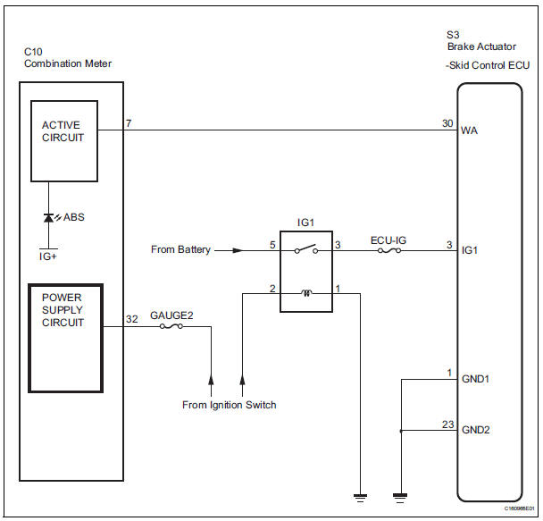
INSPECTION PROCEDURE
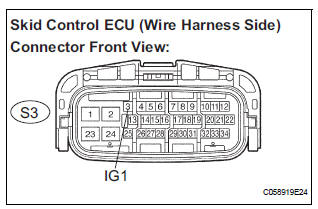
1 INSPECT SKID CONTROL ECU CONNECTOR IS SECURELY CONNECTED
(a) Check the skid control ECU connector's connecting condition.
OK: The connector should be securely connected.

2 INSPECT BATTERY
(a) Check the battery voltage.
Standard voltage: 11 to 14 V

2 INSPECT BATTERY
(a) Check the battery voltage.
Standard voltage: 11 to 14 V


3 INSPECT SKID CONTROL ECU (IG1 TERMINAL VOLTAGE)
(a) Disconnect the skid control ECU connector.
(b) Turn the ignition switch to the ON position.
(c) Measure the voltage according to the value(s) in the table below.
Standard voltage 

4 INSPECT SKID CONTROL ECU (GND TERMINAL CONTINUITY)
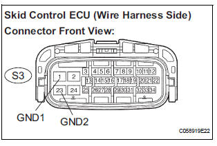
(a) Turn the ignition switch off.
(b) Measure the resistance according to the value(s) in the table below.
Standard resistance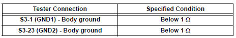

5 CHECK HARNESS AND CONNECTOR (BETWEEN SKID CONTROL ECU AND COMBINATION METER ASSEMBLY)
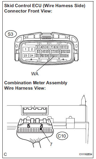
(a) Disconnect the combination meter connector.
(b) Measure the resistance according to the value(s) in the table below.
Standard resistance 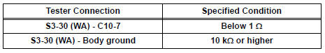

6 INSPECT COMBINATION METER ASSEMBLY
(a) Check the combination meter (See page ME-4).
HINT: If troubleshooting has been carried out according to the PROBLEM SYMPTOMS TABLE, refer back to the table and proceed to the next step before replacing the part (See page BC-7).

REPLACE BRAKE ACTUATOR ASSEMBLY
 Open in Pump Motor Circuit
DTC C1251/51 Open in Pump Motor Circuit
DESCRIPTION
The motor relay (semiconductor relay) is housed in the brake actuator
assembly and drives the pump
motor based on a signal from the skid contro ...
 ABS Warning Light does not Come ON
WIRING DIAGRAM
See page BC-47.
INSPECTION PROCEDURE
1 INSPECT ABS WARNING LIGHT
(a) Disconnect the skid control ECU connector.
(b) Turn the ignition switch to the ON position.
(c) Check that ...
Other materials:
DVD Error/ Excess Current/ Tray Insertion / Ejection Error
DTC 44-44 DVD Error
DTC 44-48 Excess Current
DTC 44-50 Tray Insertion / Ejection Error
DESCRIPTION
DTC No.
DTC Detecting Condition
Trouble Area
44-44
Operation error in the DVD mechanism.
Television display assembly
44-48
Excess current is ...
Terminals of ECU
1. CHECK DRIVER SIDE J/B ASSEMBLY (MULTIPLEX NETWORK BODY ECU)
Disconnect the B6, 1C, 1K and 1L J/B connectors.
Measure the voltage and resistance according to
the value(s) in the table below.
HINT:
If the result is not as specified, there may be a
malfunction on the w ...
Crankshaft Position - Camshaft Position Correlation
DTC P0016 Crankshaft Position - Camshaft Position Correlation
(Bank 1 Sensor A)
DTC P0017 Crankshaft Position - Camshaft Position Correlation
(Bank 1 Sensor B)
DTC P0018 Crankshaft Position - Camshaft Position Correlation
(Bank 2 Sensor A)
DTC P0019 Crankshaft Position - Camshaft Position Corr ...
