Toyota Sienna Service Manual: ABS Warning Light Remains ON
DESCRIPTION
If any of the following is detected, the ABS warning light remains on.
- The skid control ECU connectors are disconnected from the skid control ECU.
- There is a malfunction in the skid control ECU internal circuit.
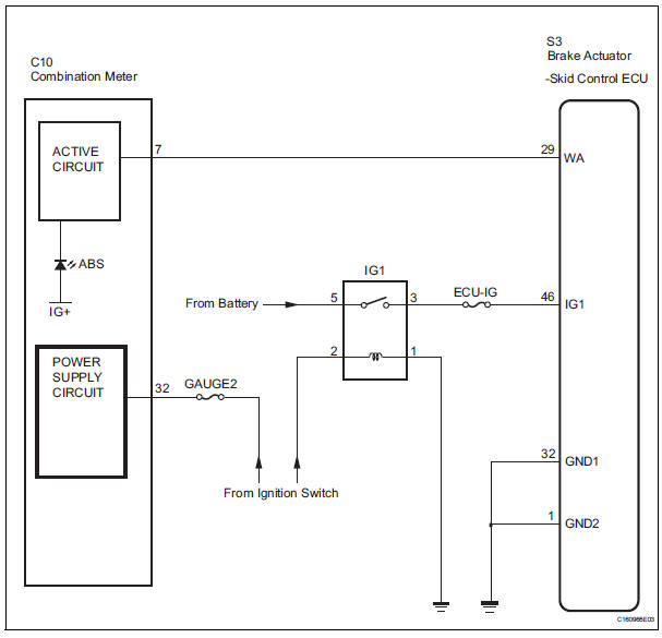
- There is an open in the harness between the combination meter and the skid control ECU.
HINT: In some cases, the intelligent tester cannot be used when the skid control ECU is abnormal.
WIRING DIAGRAM
INSPECTION PROCEDURE
1 CHECK DTC
(a) Is DTC output for ABS?
Result 

2 CHECK IF SKID CONTROL ECU CONNECTOR IS SECURELY CONNECTED
(a) Check the ECU connector's connecting condition.
OK: The connector should be securely connected.

3 CHECK BATTERY
(a) Check the battery voltage.
Standard voltage: 11 to 14 V

4 INSPECT SKID CONTROL ECU (IG1 TERMINAL)
(a) WHEN USING INTELLIGENT TESTER: (1) Connect the intelligent tester to the DLC3.
(2) Start the engine.
(3) Select the DATA LIST mode on the intelligent tester.
ABS / VSC: 
(4) Read the voltage condition output from the ECU displayed on the intelligent tester.
OK: "Normal" is displayed.
(b) WHEN NOT USING INTELLIGENT TESTER:
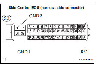
(1) Disconnect the skid control ECU connector.
(2) Turn the ignition switch to the ON position.
(3) Measure the voltage according to the value(s) in the table below.
Standard voltage 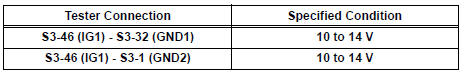


5 CHECK ABS WARNING LIGHT
(a) WHEN USING INTELLIGENT TESTER: (1) Connect the intelligent tester to the DLC3 and start the engine.
(2) Select the item "ABS WARN LIGHT" in the ACTIVE TEST and operate the ABS warning light on the intelligent tester.
(3) Check that "ON" and "OFF" of the ABS warning light can be shown on the combination meter by the intelligent tester.
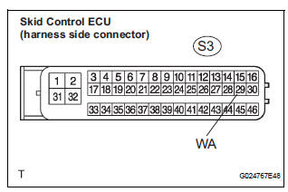
(b) WHEN NOT USING INTELLIGENT TESTER: (1) Turn the ignition switch off and disconnect the connector from the skid control ECU.
(2) Ground the terminal WA of the skid control ECU.
(3) Turn the ignition switch to the ON position.
(4) Check that the ABS warning light goes off.

REPLACE BRAKE ACTUATOR ASSEMBLY
6 CHECK HARNESS AND CONNECTOR (SKID CONTROL ECU - BODY GROUND)
(a) Disconnect the skid control ECU connector.
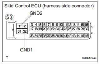
(b) Measure the resistance according to the value(s) in the table below.
Standard resistance 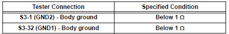
NOTICE: When replacing brake actuator assembly, perform zero point calibration (See page BC-70).

REPLACE BRAKE ACTUATOR ASSEMBLY
 Steering Angle Sensor Zero Point Malfunction
DTC C1290/66 Steering Angle Sensor Zero Point Malfunction
DESCRIPTION
The skid control ECU acquires steering angle sensor zero point every time the
ignition switch is turned to
the ON position an ...
 ABS Warning Light does not Come ON
WIRING DIAGRAM
Refer to ABS Warning Light Remains ON (See page BC-141).
INSPECTION PROCEDURE
1 CHECK ABS WARNING LIGHT
(a) Disconnect the skid control ECU connector.
(b) Turn the ignition switc ...
Other materials:
Installation
HINT:
Install the RH side by same procedure as the LH side.
1. INSTALL REAR SPEED SENSOR
(a) Install the speed sensor rear LH with the bolt.
Torque: 8.0 N*m (82 kgf*cm, 71 in.*lbf)
NOTICE:
Keep the tip of the speed sensor rear LH clean.
(b) Install the sensor harness clamps with the b ...
Removal
1. REMOVE REAR WHEEL
2. REMOVE REAR SHOCK ABSORBER CAP LH
(a) Remove the shock absorber head cover.
(b) Remove the shock absorber cap LH.
3. REMOVE SHOCK ABSORBER ASSEMBLY REAR LH
(a) Support the rear axle beam with a jack.
(b) Using a 6 mm hexagon wrench to hold the piston
rod, ...
Check and replace ecu
NOTICE: • The connector should not be disconnected from
the ECU. Perform the inspection from the
backside of the connector on the wire harness
side.
• When no measuring condition is specified,
perform the inspection with the engine stopped
and the ignition switch on.
• Che ...
