Toyota Sienna Service Manual: Accelerator pedal rod
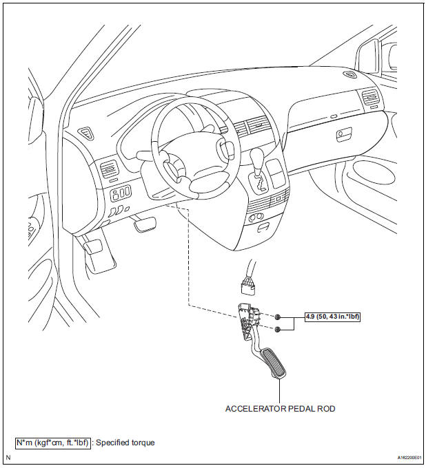
COMPONENTS
ON-VEHICLE INSPECTION
1. CHECK ACCELERATOR PEDAL ROD
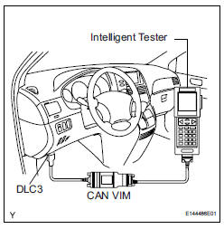
(a) Check the voltage.
(1) Connect the intelligent tester to the DLC3.
(2) Turn the ignition switch to the ON position.
(3) Turn the intelligent tester on.
(4) Select the menu items: DIAGNOSIS / ENHANCED OBD II / DATA LIST / ALL / ACCEL POS #1, ACCEL POS #2.
(5) Operate the accelerator pedal, and then check that the ACCEL POS #1 and ACCEL POS #2 values are within the specifications.
Standard voltage (ACCEL POS #1)
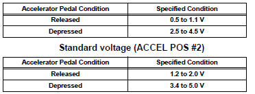
If the result is not as specified, check the accelerator pedal rod, wire harness or ECM.
REMOVAL
1. REMOVE ACCELERATOR PEDAL ROD
(a) Disconnect the accelerator pedal position sensor connector.
(b) Remove the 2 nuts and accelerator pedal rod.
INSTALLATION
1. INSTALL ACCELERATOR PEDAL ROD
NOTICE:
|
(a) Install the accelerator pedal rod with the 2 nuts.
Torque: 4.9 N*m (50 kgf*cm, 43 in.*lbf) (b) Connect the accelerator pedal position sensor connector.
 ECM
ECM
COMPONENTS
REMOVAL
1. REMOVE GLOVE COMPARTMENT DOOR ASSEMBLY
(a) Push the right side wall and then push the left wall
to release the stoppers.
(b) Pull the glove compartment door sub-as ...
 Mass air flow meter
COMPONENTS
ON-VEHICLE INSPECTION
1. INSPECT MASS AIR FLOW METER
NOTICE:
Perform the mass air flow (MAF) meter inspection
by following the procedures below.
Only replace t ...
Other materials:
Knock Sensor Circuit Low Input/ Knock Sensor Circuit High Input
DTC P0327 Knock Sensor 1 Circuit Low Input (Bank 1 or
Single Sensor)
DTC P0328 Knock Sensor 1 Circuit High Input (Bank 1 or
Single Sensor)
DTC P0332 Knock Sensor 2 Circuit Low Input (Bank 2)
DTC P0333 Knock Sensor 2 Circuit High Input (Bank 2)
DESCRIPTION
A flat type knock sensor (non-resona ...
System description
1. DESCRIPTION OF OCCUPANT CLASSIFICATION SYSTEM
GENERAL DESCRIPTION.
In the occupant classification system, the
occupant classification ECU calculates the
weight of the occupant based on a signal from
the occupant classification sensors. This system
recognizes the occu ...
Rear door lock
INSPECTION
1. INSPECT REAR DOOR LOCK ACTUATOR ASSEMBLY LH
Apply battery voltage to the door lock and check
operation of the motor.
OK
HINT:
If the result is not as specified, replace the door lock
assembly.
Measure the resistance according to the value(s) in
the ...
