Toyota Sienna Service Manual: Accessory meter
COMPONENTS
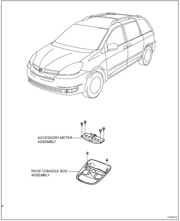
 Installation
1. INSTALL COMBINATION METER ASSEMBLY
Connect the connectors.
Install the combination meter assembly with the 4
screws.
2. INSTALL INSTRUMENT CLUSTER FINISH PANEL SUB-ASSEMB ...
 Calibration
1. SELECT COMPASS DISPLAY MODE
The MODE switch allows you to select the Display
or Non-display mode of the compass.
HINT:
In compass display mode, the display indicates
outside temper ...
Other materials:
Terminals of ECU
1. RADIO AND NAVIGATION ASSEMBLY
*1: with Rear Seat Entertainment System
Reference: waveform 1
HINT:
Terminal: VV+ - VV-
Gauge set: 200 mV/DIV, 10 μs/DIV
Condition: DVD is played on radio and navigation
assembly
Reference: wave ...
Engine Immobiliser System Malfunction
DTC B2799 Engine Immobiliser System Malfunction
DESCRIPTION
This DTC is output when the ECM detects errors in communication between the
transponder key ECU
and the ECM, or in the communication lines. This DTC is also output when an
engine start is attempted
while the ECU communication ID bet ...
Air outlets
Location of air outlets
The air outlets and air volume
changes according to the
selected air flow mode.
Adjusting the position of the air outlets
Direct air flow to the front or
rear, up or down.
Temperature display
The temperature display on the multi-information display can be chan ...
